
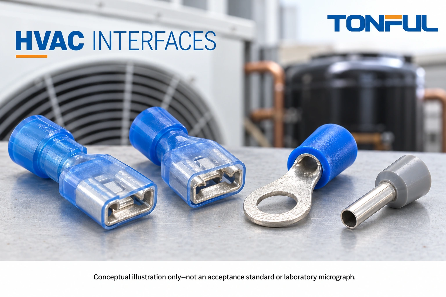
HVAC terminal selection must account for the equipment interface, electrical duty and installed environment together. A replacement that fits a tab may still have the wrong retention, insulation envelope or wire accommodation. In rooftop and outdoor equipment, a connection also experiences service handling, moisture paths and repeated changes in temperature.
The useful purchasing question is not which terminal is strongest in general. It is which documented termination system matches this fan, compressor or control connection, and what evidence allows its release. Begin with the equipment manufacturer’s drawing and service instructions, then document the wire, terminal, mating interface and assembly process as one combination.
Jump to: Safety and scope | Interface matrix | Environment | Tooling | Approval | Sourcing
Set the HVAC Safety and Design Boundary
Separate factory equipment wiring from field-installed supply wiring and external controls. Their documentation and installation responsibilities may differ. Identify the equipment model, circuit reference and original part before considering an alternative. A terminal used on a control relay does not automatically qualify for a compressor connection or incoming power termination.
Require a Verified Safe Condition
Line-voltage HVAC work is for qualified personnel following the applicable isolation, lockout and stored-energy procedure. Equipment may have multiple supplies, automatic restart, inverter electronics and capacitors. Follow the manufacturer’s procedure to establish and verify a safe condition before handling wiring. This guide does not provide capacitor discharge or live diagnostic instructions.
The OSHA electrical work-practice requirements address deenergization and hazardous stored energy. Their US workplace scope is not a replacement for local requirements or equipment-specific instructions. Never connect a continuity or resistance instrument to an energized circuit.
Protect the Compressor Boundary
Treat compressor terminal assemblies, protective covers and connection systems as OEM-controlled interfaces. Do not improvise a receptacle, force a connector onto a pin, bypass protection or alter a terminal plate. A damaged compressor terminal area needs the manufacturer’s assessment and approved repair process, not a generic assortment-kit substitution.
Record whether the candidate is an original replacement, an engineering-approved alternative or a new production design. These are different approval routes. Purchasing should keep an unapproved alternative out of maintenance stock even when its dimensions appear similar.
HVAC Terminal Selection by Equipment Interface
Define the mating point before choosing insulation or wire range. Tab width alone is incomplete for blade receptacles; mating thickness, engagement, retention feature and installed clearance also matter. Stud-based connections require the drawing-defined hole, hardware and tightening instruction. Clamp terminals require the equipment’s accepted conductor preparation.
| HVAC location | Information to obtain | Selection decision | Reason to stop release |
|---|---|---|---|
| Fan motor lead | Motor interface, routing, movement and lead specification | Match approved receptacle, ring or housing contact | Unknown mating dimensions or unsupported substitution |
| Compressor connection | Exact compressor connection system and cover | Use OEM-defined system or authorized alternative | Damaged terminal area or missing OEM approval |
| Contactor or relay | Tab geometry, switching duty and enclosure space | Match terminal and protective insulation arrangement | Incomplete seating or side-loaded connection |
| Control clamp | Accepted wire type, strip length and ferrule instruction | Use documented bare-wire or ferrule preparation | Clamp instructions unavailable |
| External control cable | Circuit classification, entry and moisture exposure | Select interface and enclosure as a system | Wrong field-wiring method or unverified exposure claim |
Separate Power and Signal Decisions
Power circuits need review of the intended load, operating duty and local temperature within the equipment evaluation. Sensor and communication circuits need correct conductor identity, contact suitability, routing and protection from misconnection. Do not rank every terminal by conductor size and overlook its role in a low-level signal circuit.
TONFUL’s wire terminal manufacturing overview can help identify product families for a feasibility discussion. It cannot establish compatibility with a specific HVAC OEM. Require a candidate part number and its own documentation before using a catalog family name in an approved bill of materials.
Review Condensation, Routing and Service Access
An outdoor cabinet is not automatically dry inside. Temperature changes, cable entries, nearby coils and drainage arrangements can influence where moisture reaches a connection. Map those paths before deciding whether a protected unsealed termination is acceptable or a documented sealed system is needed.

Insulation Is Not a Seal
An insulating sleeve prevents certain contact exposures only within its design; it does not inherently seal the wire entry or mating interface. An added boot or sleeve can also trap moisture or obstruct inspection if it is not part of the approved arrangement. Obtain installation instructions for the whole protective system, including cable entry and strain relief.
The nylon-insulated terminal category offers candidates for insulated applications, but the category title is not evidence of wet-location suitability. Where a protected internal connection uses a non-insulated terminal, the equipment design still controls guarding, spacing and environmental protection.
Manage Movement and Access
Check cable support near fans, vibrating assemblies and removable panels. Harness movement should not repeatedly bend the conductor at the crimp exit or load the mating interface. Review the installed routing with guards fitted, not only during an open-cabinet bench review.
Service access creates another load case. A technician must be able to identify the connection and release it by the intended method without pulling the wire or damaging adjacent parts. Mark circuits and connector positions according to the equipment documentation. Sleeve color is neither a circuit identifier nor proof of polarity.
Keep a record of the planned removal path and whether a replacement cover, locking feature or other consumable is needed. A lower unit-price terminal can create an unsuitable service method if the approved interface cannot be disconnected and restored correctly in the available space.
Control the Wire, Terminal and Tool Combination
Treat the termination as a controlled combination of wire construction, terminal, preparation and tooling. The wire specification should identify conductor material, area, stranding and insulation dimensions. Two wires with the same nominal area can need different barrel accommodation or insulation support.
Confirm Clamp and Ferrule Compatibility
TONFUL’s cord end terminal range is relevant only when the HVAC control terminal accepts that conductor preparation. Confirm sleeve length, collar clearance, crimp profile and insertion depth against the clamp instructions. Do not add a ferrule simply because the conductor is stranded, and do not put two wires in a single ferrule unless the component combination is explicitly permitted.
For blade, ring and other crimp terminals, use the approved application specification for strip length, crimp position and inspection criteria. Do not remove strands to make a conductor fit or alter a terminal’s mating feature to accommodate a different tab. A forced fit hides a selection problem rather than solving it.
Specify Tool Identity
Discuss the exact part with TONFUL’s crimping tool team and request the recommended tool, die or cavity and setup instruction. Tool color markings and approximate jaw shape are not an application specification. Record the tool used for samples and the proposed production or service tool separately.
Define setup verification and the reaction to a failed check. Stop and segregate affected work when preparation, crimp placement or mating engagement is outside the approved criteria. Repeatedly squeezing an unacceptable crimp is not a controlled repair unless the governing instructions explicitly allow that operation.
Use a Sample and Maintenance Handover Record
Approve a representative installed arrangement before releasing a new production combination or authorized substitution. Include the mating equipment part, actual wire and routing constraints. The sample plan should state quantities, acceptance-source documents, conditioning and required checks before samples are made; there is no universal quantity that proves every HVAC application.

Record Evidence That Another Team Can Use
| Handover field | Required entry | Owner to identify |
|---|---|---|
| Equipment identity | OEM, model, revision and circuit reference | Equipment engineering |
| Termination configuration | Terminal, mating part, wire and protective components | Design engineering |
| Assembly method | Tool, cavity, preparation and inspection instruction | Manufacturing or service engineering |
| Application review | Duty, environment, routing and interface evidence | Responsible technical reviewer |
| Acceptance source | Drawing, specification and report references | Quality |
| Service disposition | Approved replacement route and excluded substitutions | Maintenance planning |
| Change status | Open items, affected lots and release authorization | Change-control owner |
The table is a proposed record template, not a claim that TONFUL has tested an HVAC assembly. Where mechanical, electrical or environmental evaluations are required, the approved plan must define conditions and acceptance criteria. A visual inspection can confirm seating and routing but cannot establish every aspect of load or moisture performance.
Investigate Damage Before Replacing Parts
When a connection shows discoloration, looseness or insulation damage, preserve its identity and condition before removal under the safe-work procedure. Record the terminal, mating part, wire, circuit location and affected equipment. Treat the visible symptom as a reason for investigation, not proof that one terminal material caused the problem.
Check the mating interface and adjacent wire condition as well as the removable terminal. Replacing only one damaged side can leave the original defect in service. Engineering should define containment, repair scope and the evidence needed to return the equipment to operation. Do not bypass a protection device to see whether the replacement works.
Separate Service Stock From Development Parts
Keep engineering samples and unapproved alternatives out of the service-parts bin. Label their status so that an urgent equipment outage does not turn a trial component into an undocumented replacement. The maintenance system should link each approved service item to its equipment applicability, instructions and required accompanying parts. Where one sales description covers several revisions, retain the identifier that distinguishes the approved configuration. Review stock after an OEM change or a supplier notification, and quarantine items whose applicability is unresolved. This is an inventory control for the approval boundary, not a claim that every HVAC system uses the same replacement policy.
Send TONFUL an Interface-Specific Inquiry
Provide TONFUL with the equipment interface drawing, actual wire construction, circuit function and local environment. Identify whether the request concerns factory production, an OEM-authorized replacement or a feasibility study. State clearly when the compressor connection system is outside the substitution scope.
Request candidate drawings, relevant material and approval documentation, tool recommendations and a sample proposal tied to the handover record. Ask the supplier to list unresolved compatibility questions rather than marking the application universally suitable. Supply terms and custom options should be confirmed for the actual project, not inferred from a broad catalog page.
Before ordering production stock, agree the notification and approval process for changes in terminal construction, plating, insulation, tooling and source. Share the completed interface matrix with TONFUL for a documented review, then retain final release responsibility with the equipment engineering team and the applicable OEM approval process.