
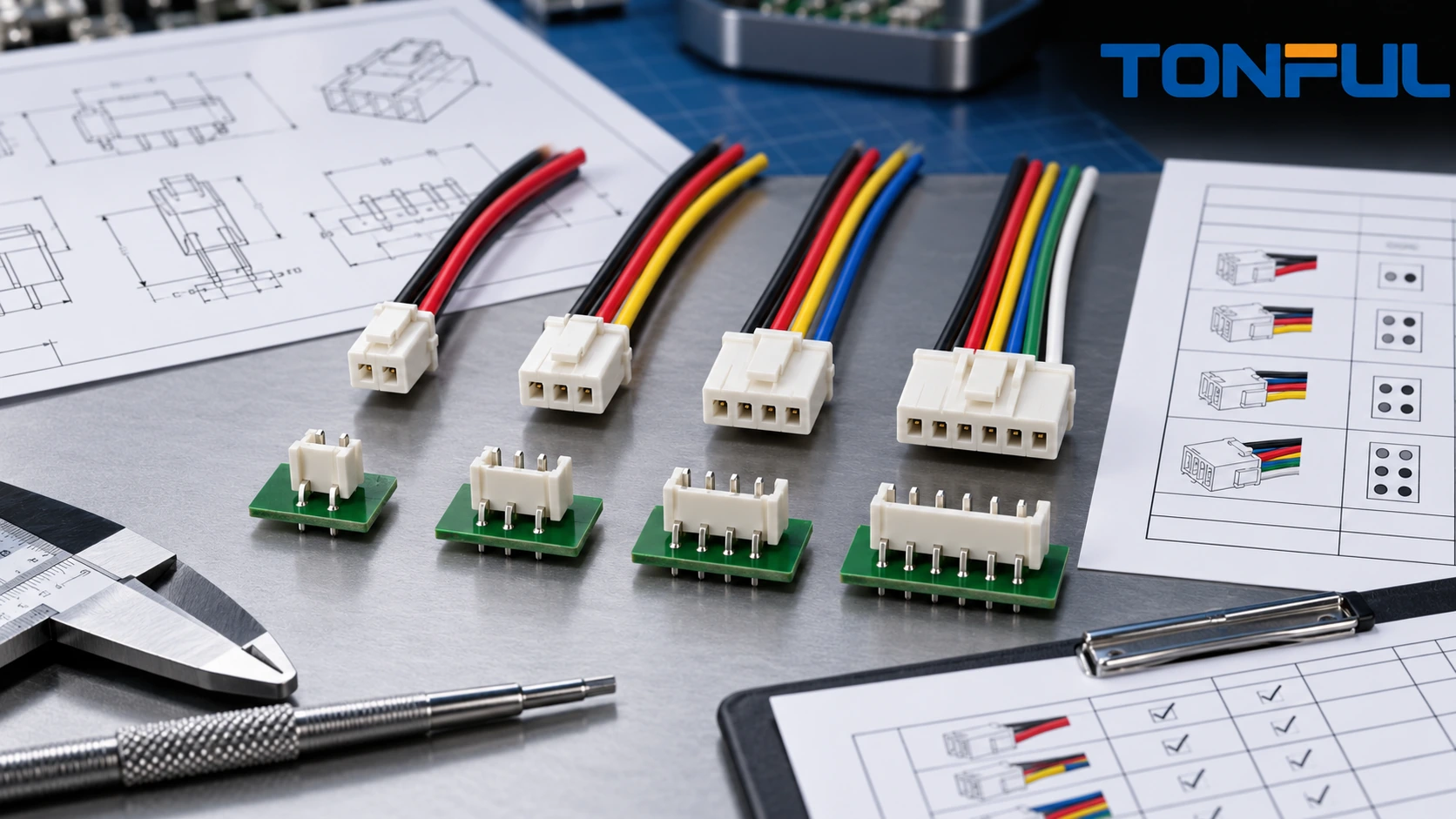
Discrete wire and PCB pigtail assemblies connect a printed circuit board to switches, sensors, motors, displays, power inputs or a second subassembly. They may contain only a few wires and one compact housing, but a small dimensional or orientation error can reverse polarity, shift every circuit by one cavity or place stress directly on a board-mounted header.
Pitch is only one attribute of a wire-to-board system. Two connector families can share the same nominal centerline while differing in housing keys, latch position, terminal geometry, plating, mating depth, current capability and PCB header dimensions. A reliable pigtail therefore starts with a controlled mating system and board interface, not a generic description such as “2.0 mm plug.”
This guide covers crimped discrete-wire pigtails that mate to PCB headers or terminate at another controlled interface. Direct-solder wire tails, flat-flex cables and ribbon-cable IDC assemblies need different process controls.
Define the Board Interface Before the Cable
Identify the board assembly number and revision, header manufacturer and part number, mounting orientation, number of circuits, loaded positions and mechanical envelope. Record whether the header is vertical or right-angle, through-hole or surface-mount, shrouded or exposed, latched or friction-locking. If the PCB is still under development, freeze the connector family before approving the pigtail drawing.
The board drawing should define the pin-one reference and the mating-face orientation. The pigtail drawing should use the same datum or clearly translate it. Terms such as “left,” “right,” “top” and “bottom” are unreliable unless the viewing direction is stated. Use labeled mating-face and wire-side views, plus a key or latch datum.
A general custom wire harness buying guide helps establish circuit and environment inputs, but a PCB pigtail requires additional board-level fields:
- Header and mating-housing controlled part numbers.
- Circuit count, populated cavities and intentionally empty positions.
- Header orientation, pin-one marker and board revision.
- Mating clearance and withdrawal access.
- Wire exit direction, bend space and strain-relief boundary.
- Electrical function and permitted load for each board pin.
- Ground, shield or chassis-reference treatment where applicable.
Why Connector Pitch Does Not Prove Compatibility
Pitch is the center-to-center spacing between adjacent positions. It helps describe connector density, but it does not identify a complete interconnect system. A housing from one family may appear to fit another header yet have different contact engagement, polarization or latch retention. Forcing an unapproved combination can damage contacts or create intermittent engagement.
The official Molex wire-to-board connector overview illustrates why the family matters: its systems span different pitch, circuit count, wire size, mounting and retention approaches. Use that source as evidence that wire-to-board architectures vary, not as permission to substitute one family for another.
Control at least these matched elements:
| Interface element | Required identification | Why it matters |
|---|---|---|
| PCB header | Manufacturer, family, full part number, revision | Establishes board footprint and mating geometry |
| Cable housing | Manufacturer and full part number | Controls keying, latch and cavity layout |
| Crimp terminal | Full part number and plating | Controls wire range and contact interface |
| Secondary lock/retainer | Part number and installed position | Helps control terminal seating where designed |
| Wire | Construction, conductor size, insulation OD and lot | Must match terminal and application |
| Mating pair | Approved combination and evidence source | Prevents cross-family assumptions |
Do not call a connector “JST-style,” “Molex-style” or “compatible” on a production drawing. Use the exact approved family and component numbers or a separately qualified alternative set.
Build a Pinout and Polarity Matrix
Every cavity should appear in the circuit table, including unused positions. Record connector ID, cavity, board pin, circuit name, wire color, wire specification, opposite endpoint and special instruction. If polarity matters, identify positive, return and protective or chassis references explicitly rather than relying on color alone.

Conceptual connector-orientation diagram showing the evidence needed to prevent mirrored pinouts; the approved drawing remains the acceptance source.
| Connector | Cavity | Board pin | Circuit/function | Wire | Opposite endpoint | Verification |
|---|---|---|---|---|---|---|
| J1 | Enter | Enter | Enter | Spec/color | Enter | Continuity map |
| J1 | Enter | Enter | Enter | Spec/color | Enter | Continuity map |
| J1 | Enter | Enter | Enter | Spec/color | Enter | Continuity map |
If the pigtail includes LEDs, diodes, thermistors, resistors or other polarity-sensitive components, add a schematic and orientation instruction. Do not expect a continuity tester to interpret every embedded component correctly without a controlled fixture and program. The drawing and pinout interpretation guide provides a conflict-control method when the schematic, cable drawing and board silkscreen disagree.
Specify Wire, Length and Routing as Installed
Select each wire using circuit current, voltage, temperature, flexibility, insulation compatibility, termination range and applicable end-product requirements. Short pigtails often operate near heat-generating components or sharp board edges, so include local temperature zones and routing constraints rather than using only ambient room temperature.
Define length between named datums. A housing-back-to-terminal-tip dimension differs from a cut-wire length or exposed-tail dimension. State tolerance, breakout point, twist requirement, sleeve position, label location and whether the assembly is measured straight or in a fixture. If multiple wires enter a common sleeve, control where the bundle begins and whether individual service loops are required.
Routing affects the board connector. Avoid a bend that starts immediately at the housing and continuously pulls the latch or terminals. Define minimum free length, bend direction, support point and installation sequence from the actual equipment model. A harness clip or tie should support the bundle without creating a hard point at the wire exit.
Control Crimping and Terminal Insertion
The terminal, conductor and insulation must be treated as a qualified combination. The crimp setup should reference the terminal supplier’s application data, approved conductor construction, insulation OD, applicator, press, setup and inspection method. Generic wire gauge alone does not prove compatibility because conductor stranding and insulation geometry vary.
Production controls commonly include:
- Correct terminal and wire lot verification.
- Strip length and no-cut-strand criteria.
- Conductor and insulation crimp dimensions from the acceptance source.
- Bellmouth, brush, seam and insulation-support inspection where applicable.
- Applicator and press identity, setup approval and maintenance status.
- Crimp-height measurement and pull testing at defined frequencies.
- Reaction plan for out-of-control results.
After crimping, insert each terminal in the specified orientation until its primary lock engages. Apply the secondary lock or retainer only as designed; it should not be used to force a partly seated terminal into position. Visual or tactile confirmation alone may be insufficient for small housings. Use cavity-level inspection and a controlled push/pull or seating check appropriate to the connector system.
The connector selection guide explains why a substitute housing also requires contact, tooling and validation review rather than a BOM-only change.
Distinguish Three Retention Interfaces
“Retention” can refer to different mechanical paths. Specify and test the one that matters instead of reporting a single unlabeled pull value.
- Wire-to-terminal crimp retention: evaluates the crimped conductor and, where applicable, insulation support under a controlled method.
- Terminal-to-housing retention: checks whether the seated terminal remains captured by the housing lock and secondary lock.
- Housing-to-header mating retention: evaluates the mated connector latch or friction interface.

Conceptual illustration separating crimp, terminal-to-housing and connector-mating retention; project documents define fixtures, loads and acceptance values.
For each test, record sample ID, conditioning, pull direction, fixture, test speed, equipment range and accuracy, peak result, failure mode and acceptance source. A pull applied at an angle can load the housing wall rather than the intended lock. Do not convert a terminal supplier’s component value into a universal finished-assembly limit.
Inspect the PCB Header and Mating Clearance
A compliant cable-side assembly can still fail when the board header is wrong, tilted, poorly soldered or obstructed. During first-article and installed-sample review, inspect header part number, orientation, seating to the board, solder condition, latch access, pin damage and nearby component clearance. Confirm that the operator can mate and release the connector without pulling wires or levering against components.
The cable supplier may not control PCB manufacture, so record the interface boundary. If the PCB header changes, require a compatibility and sample review even when pitch and circuit count remain unchanged. Header plating, plastic geometry, pin length, polarization and solder-tail configuration can affect the complete interface.
Use Electrical Tests That Match the Assembly
Routine production tests should at minimum verify the approved pin map and detect specified opens, shorts and miswires. The fixture must identify each connector orientation and prevent a reversed housing from producing a false pass. For polarized power circuits, add an explicit polarity decision rather than relying on net names.
Where resistance matters, define test current, two-wire or four-wire method, Force/Sense locations, reference-wire treatment, ambient temperature, instrument capability and acceptance document. Continuity thresholds chosen only for fast throughput may hide a high-resistance crimp or contact. The continuity, insulation-resistance and hi-pot guide keeps each test’s purpose and safety boundary separate.
Functional testing with the PCB can confirm interface behavior, but it does not replace cable-level pin-map records. Conversely, a cable tester cannot prove firmware interpretation, sensor calibration or full equipment safety. Define which organization owns cable, board and completed-product validation.
Create a Reusable Pigtail Approval Record
| Record field | Required entry |
|---|---|
| Assembly identity | Part number, revision, lot and sample ID |
| PCB interface | Board revision, header part and orientation |
| Cable connector | Housing, terminal, retainer and cavity map |
| Wire | Part number, construction, size, OD and lot |
| Dimensions | Datum, nominal, tolerance and measured result |
| Crimp evidence | Tooling, setup, crimp result and pull result |
| Insertion evidence | Cavity seating and secondary-lock status |
| Electrical result | Pin map, polarity, shorts and conditional resistance tests |
| Installed review | Clearance, routing, latch access and strain relief |
| Disposition | Acceptance source, pass/fail, reviewer and date |
Use production-intent components and processes for sample approval. Record deviations rather than silently hand-building around tooling or clearance problems. A first article demonstrates the submitted configuration; it does not authorize future changes to header, housing, terminal, wire, tooling or factory. Link approved samples and subsequent lots using revision control and lot traceability.
RFQ and Release Checklist

A structured PCB pigtail specification keeps board, connector, wire, pinout, dimensions and acceptance records under one revision.
Before requesting a quote or releasing production, confirm:
- Board and header controlled part numbers and revisions.
- Housing, terminal, retainer and approved mating combination.
- Pitch, circuit count, keying, latch and orientation drawings.
- Complete cavity-to-board-pin matrix, including empty cavities.
- Wire specification, color, length datum and tolerance.
- Crimp tooling, application requirements and inspection plan.
- Terminal insertion, secondary lock and retention verification.
- Sleeve, labels, routing support and packaging.
- Production electrical test and conditional qualification tests.
- First-article sample quantity and installed-equipment review.
- Traceability, change notification and deviation process.
- Forecast, order quantities, tooling ownership and delivery assumptions.
TONFUL can review a controlled discrete-wire or PCB pigtail package for connector matching, manufacturability, crimp access, cavity control, fixture strategy and production records. Send the board/header reference, mating connector documents, pinout, wire schedule, dimensional drawing and validation plan for a project-specific sample and quotation discussion.
—