
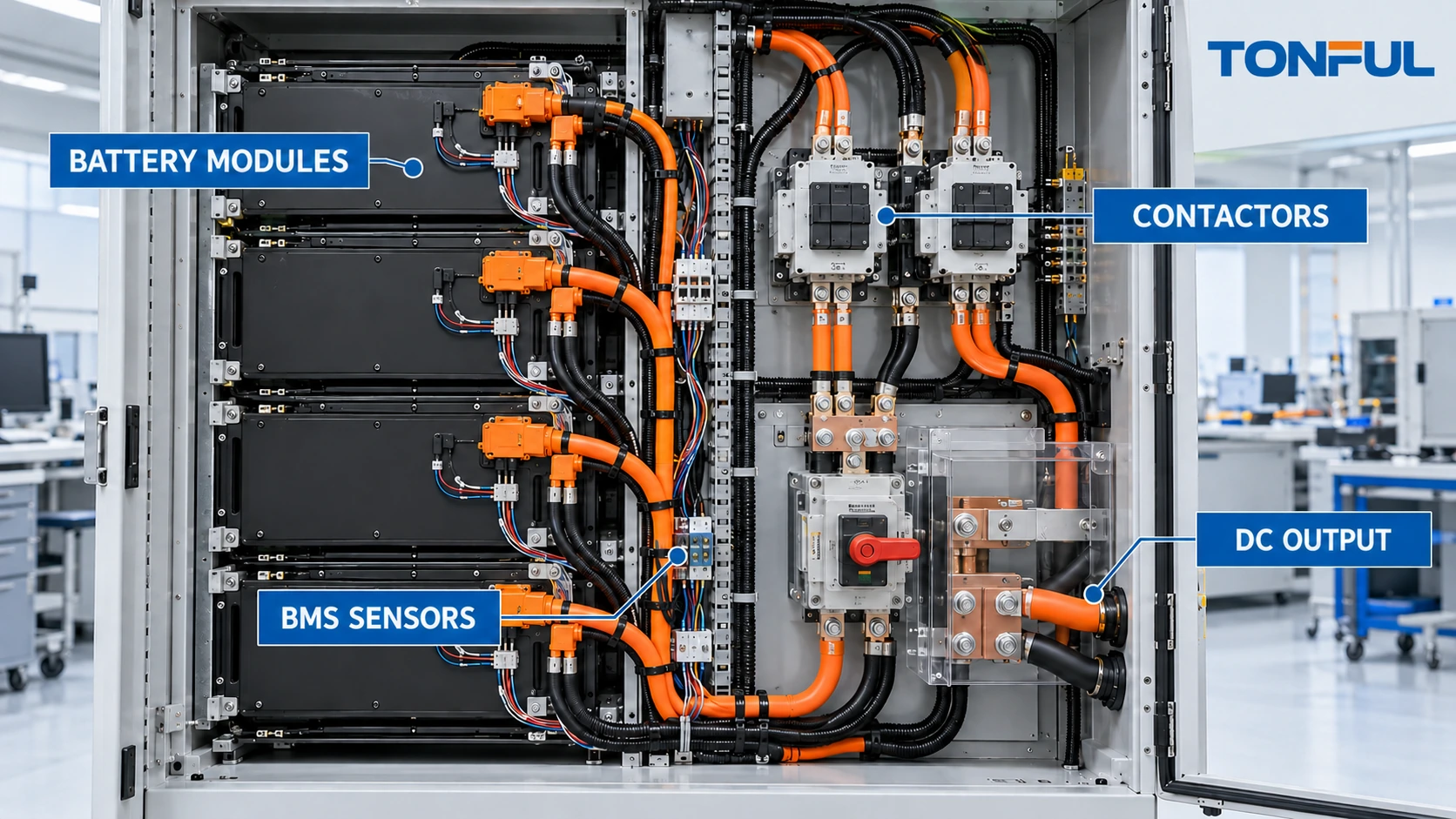
Battery and energy storage cable assemblies may carry high DC current between cells, modules, racks, contactors, fuses, disconnects, converters and external equipment. The same system can also contain low-level voltage taps, temperature sensors, current-sensor interfaces, interlocks and communication wiring. These paths have different conductor, insulation, connector, routing and test requirements.
Selecting a larger cable or a lug that fits the stud does not complete the design. The current profile, fault energy, system voltage, polarity, conductor construction, terminal interface, joint stack, thermal environment, mechanical loads and protective architecture all affect the released assembly. High-energy DC systems also require controlled de-energization and qualified work practices.
This guide focuses on cable assemblies and harnesses for stationary and industrial battery applications. It does not provide universal ampacity, torque, clearance, test voltage, temperature-rise or short-circuit values. Those limits must come from the system design, applicable standards, component documentation, installation conditions and approved validation plan.
Divide the System Into Power, Sense and Control Paths
Create an interconnect schedule that identifies every source, destination and protective boundary. Record maximum operating voltage, normal and peak current, duration, duty, fault condition, polarity and switching state where required by the design. Keep high-current links distinct from measurement and control wiring.
| Path | Key specification inputs | Typical evidence |
|---|---|---|
| Cell/module interconnect | Voltage, current, joint stack, movement and service method | Drawing, material and joint-validation record |
| Module/rack power cable | Continuous/peak current, length, conductor, insulation and protection | Voltage-drop and temperature-rise evidence |
| Contactor/fuse/disconnect link | Device terminal, fault path, switching boundary and cover | Interface drawing and protected assembly inspection |
| Converter/inverter cable | DC voltage/current, ripple, routing and termination | Load-path, thermal and installation validation |
| BMS voltage tap | Cell/module reference, protection, routing and connector cavity | Point-to-point and polarity verification |
| Temperature sensing | Sensor type, location, attachment and reference | State/response and installation evidence |
| Current/interlock/communication | Architecture, signal type, shielding/pairing and diagnostic state | Pinout and system-function test |
| Protective bonding | Attachment, conductor, hardware and path | Bonding evidence under the system plan |
The TONFUL custom cable assembly buying guide provides a structure for documenting cable construction, connectors, pinout and performance. Do not infer a safe current from cable size alone. Ambient temperature, bundling, enclosure airflow, conductor material, duty, termination, aging and installation all influence performance.
Size the Current Path From the Real Load Profile
Define continuous, transient, charging, discharging, regenerative and fault-related conditions that the project requires. Peak current without duration is incomplete; average current without cycling can hide thermal accumulation. Voltage drop and power loss depend on the complete path, including conductor, crimp, lug, bolted interface, fuse, disconnect and other joints between measurement points.
For a resistive portion of the path, heat generation follows the relationship P = I²R. A modest increase in resistance at a lug or joint can therefore create concentrated heating under high current. Conversely, increasing current raises heating with the square of current if resistance remains constant. This relationship explains why both joint quality and the actual current profile matter.
Do not turn the equation into a universal acceptance limit. The project must define test current, duration, starting temperature, sensor location, stabilization criterion, allowable rise and pass/fail source. Thermal imaging can help locate hot spots, but emissivity, reflection, camera setup and inaccessible interfaces can affect interpretation. Use contact sensors or other approved instrumentation where required.
Engineer Lugs, Crimps and Bolted Interfaces Together
A battery lug is part of a connection system, not a standalone commodity. Specify conductor material and construction, cable size, insulation diameter, lug barrel, palm geometry, hole/stud size, plating, orientation and approved crimp tooling. Confirm whether the equipment interface allows the lug thickness, palm width, bend direction and cover clearance.
Crimp controls should include strip length, conductor insertion, tool/die/cavity, setting, crimp location and visual criteria. Qualification may require crimp-height or dimensional checks, pull testing, resistance, sectioning and thermal validation according to the controlled terminal and project requirements. Production monitoring should be derived from that validated process rather than invented from a generic chart.
The bolted joint requires its own definition: stud or fastener, washer stack, contact surfaces, anti-rotation features, tightening method, tool control, torque/angle or other approved requirement, marking and rework rules. A correct crimp cannot compensate for a contaminated, loose, misaligned or incorrectly stacked bolted interface.
Where multiple lugs share a stud, define order, orientation and allowable stack height. Verify that tightening does not rotate cables into adjacent conductive parts or stress the lug barrel. Covers and barriers must fit after the cable reaches its installed position.

<figcaption><em>The conductor, crimp, lug palm, bolted stack, enclosure and measurement points form one validated current path.</em></figcaption>
Control Voltage, Insulation and Physical Protection
System nominal voltage does not fully define insulation stress. Record maximum operating voltage, transients or fault-related conditions assigned by the design, pollution/contamination environment, altitude where relevant and the protective architecture. Creepage, clearance, insulation coordination and test requirements belong to the complete system design and applicable standard set.
Cable insulation and jackets must match voltage, temperature, flexibility, abrasion, chemical exposure, flame behavior and termination process. Orange color, a thick jacket or marketing language does not prove an assembly is suitable for a particular high-voltage system. The exact cable specification and evidence must match the project.
Route power cables away from sharp edges, heat sources, moving mechanisms and service hazards. Define bend limits from the cable and system requirements; do not force a tight bend at the lug barrel. Use grommets, conduit, sleeves, clips, barriers and strain relief for specific hazards. The wire harness protection methods guide helps separate those functions.
High-energy battery work requires a controlled safe state. Follow the system manufacturer’s isolation, discharge, lockout, verification and personal-protective requirements. Only qualified personnel should probe, assemble or service energized or potentially energized circuits. Never use resistance or continuity mode on a live circuit, and never assume a disconnected control connector proves the power path is de-energized.
Keep BMS Sense Wiring Separate From Power Cabling
Voltage taps, temperature sensors, current-sensor interfaces and interlocks can influence protective decisions. Document every reference point and connector cavity. A swapped voltage tap, reversed temperature sensor or open interlock can create misleading data even when the high-current cable is correct.
Define fuse or protection elements for sense leads where the architecture uses them, along with service and replacement rules. Route sensitive circuits according to the approved system EMC and noise-control plan. Pairing, twisting, shielding and separation must be stated on the drawing rather than inferred during production.
For each BMS connector, provide a consistent end view, cavity map, wire identification and source/destination table. The guide to reading harness drawings and connector pinouts gives a practical conflict-resolution sequence. Do not energize or ground an unidentified pin.
The harness test can verify point-to-point identity, polarity, resistance-coded components or sensor states where specified. It cannot prove cell measurement accuracy, state estimation, contactor control, fault response or system functional safety. Those require integration with the BMS, battery and energy-storage system.
Validate Voltage Drop and Temperature Rise With Defined Boundaries
A useful test plan identifies exactly what is inside the measurement boundary. For a cable assembly, place sense points so the report states whether it includes conductor only, crimp interfaces, lug palms, bolted joints or mating connectors. Four-wire Kelvin methods minimize current-lead resistance, but all resistance between the two sense points remains in the reported result.
Record test current, waveform or duty, polarity, ambient and starting temperature, stabilization method, mounting, airflow, sensor position, instrument range/accuracy and calibration status. If subtracting a reference conductor or fixture value, preserve raw and corrected results and document the method. The continuity, insulation resistance and hi-pot testing guide explains why netlist, resistance and dielectric tests must not be treated as equivalents.
Thermal tests should use production-intent cable length, bends, supports, enclosures, covers and joint stacks. A bench cable in free air can underrepresent installed heating. Record the hottest conductor, crimp, lug, joint and neighboring component locations required by the plan. After conditioning, inspect for discoloration, insulation deformation, joint movement, contact damage and resistance change.

<figcaption><em>Electrical and thermal results are meaningful only when the test boundary, current profile, mounting and measurement points are controlled.</em></figcaption>
Apply Standards at the Correct System Level
The official IEC 62619:2022 specifies safety requirements and tests for secondary lithium cells and batteries used in industrial applications, including stationary applications. It is battery-level context and does not certify a cable assembly, provide universal lug limits or replace the applicable energy-storage system, installation and market requirements.
Define which evidence belongs to the cable assembly, battery module, rack, enclosure, power-conversion equipment and completed installation. Cable qualification may address conductor, termination, insulation, mechanical support and environment. The battery or storage system must separately validate protection, fault behavior, thermal management, controls, isolation, enclosure and application-specific requirements.
Production Test, Traceability and Change Control
Receiving inspection should verify cable, lugs, terminals, connectors, sleeves, covers and labels by controlled part and lot. Production controls should cover cutting, stripping, crimping, lug orientation, seal or sleeve placement, marking and electrical test. Verify tool/die/cavity, program, calibration and first-off status after setup or change.
The TONFUL wire harness manufacturing process illustrates how released materials, controlled tooling, in-process inspection and final electrical records should remain connected. Battery-cable controls should add the project-specific high-current and interface evidence described above rather than relying on a generic production traveler.
For critical bolted-interface kits, control hardware identity, surface condition, packaging and installation instructions. If assembly occurs at the customer site, define what evidence accompanies each cable and what installation record remains with the system.
Changes to conductor source, stranding, insulation, lug material/plating, tooling, cable length, route, joint stack, protective device, BMS pinout or test program require impact review. Maintain effectivity and genealogy so finished assemblies can be traced to relevant materials, processes and results.
Copyable Battery Cable Assembly Record
| Field | Required entry |
|---|---|
| System/application | Battery chemistry context, module/rack, location and market |
| Electrical boundary | Maximum voltage, continuous/peak profile, duty and protection |
| Cable | Controlled part, conductor, construction, insulation/jacket and length |
| Lug/terminal | Part, material/plating, barrel, palm, hole and orientation |
| Joint interface | Stud/fastener, stack, surface, tightening and cover requirements |
| Sense/control wiring | Source, destination, protection, pairing/shielding and pinout |
| Geometry/protection | Datums, bends, clips, grommets, barriers and service access |
| Tests | Netlist, polarity, resistance/drop, thermal and dielectric scope |
| Evidence | Samples, fixtures, instruments, raw results and acceptance source |
| Change control | Notification, effectivity, revalidation and traceability |

<figcaption><em>A controlled record connects electrical requirements, cable construction, lug interfaces, installed geometry and validation evidence.</em></figcaption>
Final Release Checklist
- Power, sensing, control, interlock and bonding paths are separately mapped.
- Voltage and current profiles include duration, duty and assigned fault conditions.
- Cable, lug, crimp tooling and bolted-interface requirements are controlled.
- Installed bends, supports, covers, barriers and service access are verified.
- BMS cavity maps, polarity and reference points are unambiguous.
- Resistance, voltage-drop and thermal tests define measurement boundaries.
- Harness evidence is separated from battery and system-level approval.
- Production records link materials, tools, processes and test results.
- Changes receive documented impact review, revalidation and effectivity.
- High-energy assembly and service procedures define a verified safe state.
Develop Battery and Energy Storage Cable Assemblies With TONFUL
For a battery cable assembly quotation, provide TONFUL with the system boundary, drawings, BOM, voltage and current profiles, conductor and lug requirements, joint interfaces, BMS pinout, routing, protection, test plan, demand and applicable requirements. TONFUL can review manufacturability, termination controls, sample records and production testing within the agreed project. Final battery, protection, energy-storage system, installation and market approval remain responsibilities of the complete program.