
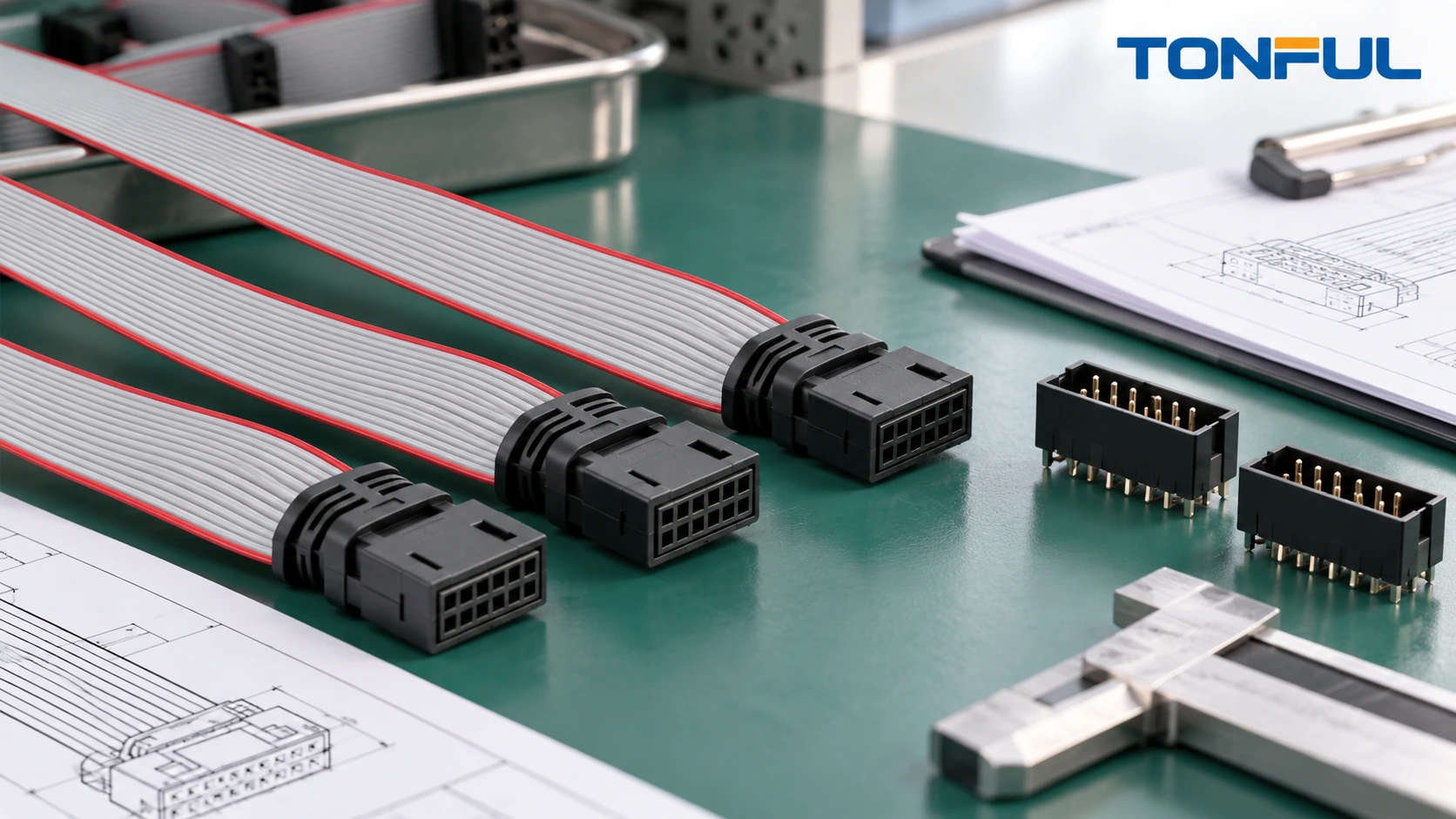
Ribbon cable assemblies organize parallel insulated conductors in a flat, repeatable layout. They can simplify internal equipment wiring between boards, displays, controls and headers, but their regular appearance also creates risk: an IDC connector can be offset by one conductor, rotated 180 degrees or installed with the wrong pin-one relationship while still looking neatly assembled.
A production-ready specification must connect four things: the ribbon cable construction, the insulation-displacement connector system, the board-header orientation and the circuit map. Pitch alone does not prove compatibility, and a colored edge stripe does not prove polarity unless the drawing defines what that stripe means at both ends.
This guide addresses passive flat-ribbon assemblies terminated with insulation-displacement connectors. Flat-flex cable, discrete-wire pigtails and high-speed twinax assemblies require different tooling and electrical controls.
Define the Complete Mating System
Record the exact cable and connector part numbers, circuit count, conductor pitch, connector centerline, contact arrangement, strain-relief components, keying and mating headers. A two-row IDC receptacle may connect alternating conductors to different contact rows, so its numbering must come from controlled connector documentation rather than an assumed left-to-right sequence.
The official TE AMP-LATCH ribbon cable connector product record shows that a connector definition includes position count, centerline, mounting orientation, polarization and controlled drawings. It supports the principle that a generic phrase such as “2.54 mm IDC” is not a complete procurement specification; the project still needs the exact approved component set.
Use the connector-control approach in choosing connectors for custom harnesses when evaluating genuine components or alternatives. A substitute requires mating, cable, tooling and validation evidence, not merely the same pitch and circuit count.
| Controlled item | Required entry | Typical risk if omitted |
|---|---|---|
| Ribbon cable | Part number, conductor count, pitch, conductor and insulation | Wrong cable-to-contact interface |
| IDC receptacle | Full part number, positions, keying and contact layout | Offset or incompatible termination |
| Strain relief | Part number and orientation | Unsupported cable at termination |
| Board header | Full part number, board revision and pin-one datum | Mirrored or rotated assembly |
| Tooling | Press, applicator/fixture and setup instruction | Uneven or incomplete displacement |
| Test fixture | Connector adapter and approved net list | False pass from mirrored mapping |
Match Cable Pitch, Conductor and IDC Contact
IDC contacts are designed around a specified cable construction. Confirm conductor pitch, conductor size and stranding, insulation material, insulation thickness and overall cable width against the connector application requirements. Do not select by nominal conductor size alone. A different insulation can change displacement behavior and conductor support even when the copper area appears similar.
Define whether the cable is standard gray, color-coded, bonded, laminated, split or otherwise processed. If individual conductors are separated for routing, specify the split length, method and allowed insulation damage. For a folded assembly, provide a controlled fold drawing and fixture because conductor order and bend direction can be reversed during manual work.
The cable’s electrical role also matters. For low-frequency control and internal power, the main requirements may be pin map, resistance, current path and routing. For faster digital interfaces, conductor spacing, adjacent ground assignment, length and connector transition can affect crosstalk and signal behavior. Do not advertise a generic ribbon assembly for a data rate or impedance without design-specific evidence.
Establish Pin One From Both Viewing Directions
Every drawing should identify connector A and B, mating-face view, cable-entry view, key/notch datum, contact numbering and cable conductor numbering. Mark conductor 1 in the cable schedule and define its relationship to the colored edge stripe. If the stripe is only a visual aid supplied by the cable manufacturer, the drawing must still control the electrical assignment.

Conceptual orientation diagram showing how pin one, the connector key and the cable edge stripe must be related by the controlled drawing.
For a straight-through assembly, state which contact at end A maps to which contact at end B. For a reversed, crossed or custom mapping, provide a complete table; never rely on terms such as “opposite orientation” without diagrams. Use the conflict-control rules in how to read a wire harness drawing and pinout when the board silkscreen, schematic and cable drawing disagree.
| End A contact | Cable conductor | Stripe relationship | End B contact | Circuit/function |
|---|---|---|---|---|
| Enter | Enter | At stripe / away from stripe | Enter | Enter |
| Enter | Enter | Enter | Enter | Enter |
| Enter | Enter | Enter | Enter | Enter |
Include every position, even unused circuits. An unconnected position can be intentional, but the tester and production operator need the same instruction.
Design the IDC Termination Process
IDC termination displaces insulation and forms an electrical interface with the conductor. The approved connector supplier’s application requirements should control cable preparation, termination height or closure position, press fixture, parallelism and inspection. Hand tools, arbor presses and production presses are not interchangeable simply because each can close the connector.
A controlled setup typically includes:
- Verified connector, cable and strain-relief lots.
- Cable cut length and square-cut requirement.
- Pin-one stripe orientation at the loading fixture.
- Connector key orientation and end identification.
- Correct press, fixture, shut height or closure control.
- Visual confirmation of full, parallel seating.
- First-piece approval after setup, tool change or restart.
- Reaction plan for incomplete seating, offset or damaged parts.
The fixture should prevent lateral offset by one or more conductors. It should also support the housing so the press load does not crack latch, polarization or strain-relief features. Inspect for skewed covers, uneven closure, exposed conductors, insulation tearing, displaced contacts and connector damage.

Conceptual IDC process illustration; the component application specification defines the actual tooling, closure and acceptance requirements.
Add Strain Relief Without Hiding Defects
Strain relief should route cable forces away from the IDC interface. Specify the component, cable fold direction, assembly sequence and finished profile. A strain-relief bar installed over a skewed connector does not correct the termination and may hide an offset cable.
Review the installed bend radius, enclosure clearance and mating/release access. Avoid a fold or clamp that loads the connector continuously. If the cable exits perpendicular to the mating direction, verify that the enclosure does not pull the receptacle out of the header when closed. For repeated flexing, a standard ribbon assembly may need additional support or a different interconnect architecture.
Branching or splitting a ribbon cable creates another transition. Define where bonding ends, how individual conductors are protected, whether a sleeve or clamp is required and how the branch is measured. The general wire harness DFM checklist can help review service loops, assembly access and support points.
Control Length, Folds and Connector Orientation
State the length datum: connector face to connector face, housing edge to housing edge, cable cut length or another named reference. Indicate whether measurement occurs with the cable flat, folded or placed in a fixture. For multiple folds, show fold sequence, direction, location, angle and finished envelope.
Do not use only a perspective image for orientation. Provide orthographic views or photographs with end identifiers and datums. If both connectors appear identical, label them physically when installation or test fixtures could swap them. A change to connector orientation can preserve electrical continuity while making the assembly impossible to install.
Packaging should prevent permanent creases at uncontrolled locations. Define coil, tray, bag, bend protection and label information. The label should preserve assembly part number, revision, lot and quantity without obscuring the pin-one stripe or interfering with routing.
Test More Than Simple End-to-End Continuity
Routine testing should verify the complete approved net list, not just that each conductor has continuity. Detect open circuits, shorts, crossed conductors, one-position offsets and unintended connections to unused positions. A keyed test adapter should establish connector orientation and prevent an incorrectly rotated part from passing because the fixture was also rotated.
For resistance-sensitive circuits, define the method, test current, fixture contribution, probe points, ambient condition and acceptance source. For insulation resistance or dielectric withstand, use only the approved voltage, dwell and connections appropriate to the cable and connected components. The continuity, insulation-resistance and hi-pot guide explains why these tests are not interchangeable.
Qualification may also include pull, flex, vibration, temperature or environmental conditioning when required by the product design. Specify sample quantity and allocation, fixtures, conditioning sequence, measurement intervals, invalid-test rules, acceptance criteria and failure analysis. Do not infer a universal cycle count from a similar-looking assembly.
Use a Practical Inspection and Test Record
| Record field | Required entry |
|---|---|
| Assembly identity | Part number, revision, lot and sample ID |
| Cable | Part number, conductor count, pitch and lot |
| Connectors | End A/B part numbers and strain-relief components |
| Orientation | Key, mating-face view and pin-one stripe result |
| Termination | Tool/fixture, setup revision and first-piece status |
| Dimensions | Datum, fold geometry, nominal/tolerance and result |
| Visual inspection | Seating, offset, damage and strain relief |
| Electrical test | Program revision, net-list result and resistance if specified |
| Qualification | Test plan, conditioning and result where applicable |
| Disposition | Acceptance source, pass/fail, reviewer and date |
First-article approval should use production-intent cable, connectors, tooling and test fixtures. Store photographs of both connector views, pin-one stripe and completed routing. Link later production to the released documents through wire harness revision control and lot traceability.
RFQ and Production Release Checklist

A controlled record aligns cable, connector, orientation, dimensions, process and test evidence before production release.
Provide the supplier with:
- Assembly number, revision and application.
- Cable manufacturer part number, count, pitch and construction.
- IDC connector and strain-relief full part numbers.
- Board-header and mating-interface references.
- Mating-face and cable-entry views with pin-one datums.
- Complete end-to-end circuit map and unused positions.
- Finished length, tolerance, folds, splits and labels.
- Termination tooling and acceptance requirements.
- Visual, dimensional and electrical test plan.
- Qualification and installed-sample responsibilities.
- Packaging, traceability, deviation and change-control rules.
- Sample quantity, forecast, order quantity and tooling ownership.
TONFUL can review a controlled ribbon cable assembly package for connector/cable matching, pin-one clarity, tooling access, dimensional feasibility and test-fixture coverage. Send the cable and connector specifications, circuit map, orientation drawing, finished geometry and acceptance plan for project-specific sample and quotation review.
—