
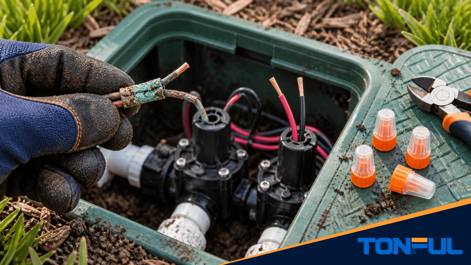
Corroded sprinkler valve wire connections can cause a valve to operate intermittently, remain closed, or appear as an electrical fault at the controller. The correct repair is not to cover the old splice with more tape or sealant. Isolate the irrigation controls, confirm the failed connection, remove corroded wire, and rebuild the splice with a waterproof connector approved for the wire combination and wet or direct-burial environment.
This guide applies to typical low-voltage irrigation control circuits with conventional station conductors, a shared common conductor, and standard non-latching valve solenoids. Decoder or two-wire systems, latching solenoids, battery controllers, and electronically managed valves can use different signaling, polarity, test equipment, and isolation procedures. Do not apply one manufacturer’s solenoid resistance range to every valve or topology. If the controller type, circuit voltage, wiring architecture, or safe test procedure is unclear, use a qualified irrigation professional or electrician.
Symptoms of a Corroded Valve Splice
- One zone works only sometimes
- A valve does not energize even though the controller activates the station
- The controller reports an open circuit or abnormal load
- Copper or connector springs show green, black, or white deposits
- Wire insulation is swollen, cracked, or wet inside
- The old splice is wrapped with deteriorated tape
- Movement of the wire causes the valve to start or stop
These symptoms can also result from a failed solenoid, broken field wire, controller output problem, or multiple bad splices. Diagnose before replacing parts.
Step 1: Shut Down and Document the Wiring

Turn off the irrigation controller and isolate its power according to the equipment instructions. Photograph and label the station wire, common wire, solenoid leads, decoder leads, and any shared splices before disconnecting them.
EPA WaterSense’s Sprinkler Spruce-Up guidance supports routine inspection of valve boxes, valves, and connections as part of irrigation maintenance. It is a water-efficiency and leak-maintenance resource, not a waterproof electrical-connector specification, multimeter procedure, or acceptance standard. Good documentation prevents a corrosion repair from becoming a wiring-error problem, but the electrical method must come from the controller, valve, solenoid, and connector manufacturers.
Step 2: Confirm the Fault Location
Inspect the connector and nearby insulation. Gently pull only on insulated wire to identify loose conductors. If testing voltage or resistance, use the controller and valve manufacturer’s procedures and a suitable meter. The Rain Bird Irrigation Troubleshooting Guide describes resistance-based fault isolation for irrigation circuits. A controller-end reading includes the station conductor, shared common path, intermediate splices, and solenoid coil; it does not identify one failed component without sectional testing.
An open, short, or unexpectedly high resistance should trigger controlled isolation. Disconnect power, identify the conductors, separate the field circuit from the controller as instructed, and test progressively at the controller, accessible splices, valve box, and solenoid. A shared common-wire defect can affect several zones. Manufacturer resistance examples apply only to the stated products, wiring arrangement, cable length, temperature, and method; use the exact valve or solenoid documentation for acceptance.
Separate electrical diagnosis from hydraulic diagnosis. A valve that receives the correct electrical command may still fail because of debris, diaphragm damage, pressure, or mechanical blockage.
Step 3: Remove the Entire Damaged Splice

Cut off the old connector. Trim each wire until the conductor is clean and bright across the full cross-section. On stranded wire, corrosion can travel between strands beyond the visible end. Replace a longer section if necessary.
Do not scrape severe corrosion and reuse the same end. Reduced conductor area, damaged strands, or remaining oxide can create a high-resistance connection.
If trimming removes too much slack, add compatible irrigation wire with two approved waterproof splices. Avoid tension on solenoid leads.
Step 4: Choose a Waterproof Connector
The connector must accept the exact combination of station wire, common wire, and solenoid lead. Check:
- Number and size of conductors
- Solid or stranded construction
- Copper compatibility
- System voltage
- Valve-box, wet-location, below-grade, or direct-bury approval
- Strip length and installation method
- Single-use instruction
Start with TONFUL’s waterproof wire nut range and selection guide. Do not choose by connector color alone.
Rain Bird DV/DVF valve installation instructions provide a product-level example of the required selection logic: use direct-burial wire and watertight connectors where the specific manual requires them. Review the exact valve instructions rather than extending one requirement to every irrigation product. An ordinary indoor wire nut wrapped with tape does not become a manufacturer-approved watertight connection.
Step 5: Rebuild the Connection
- Strip each wire to the product specification.
- Keep conductors clean and dry enough for installation.
- Align or pre-twist only as directed.
- Insert every conductor fully into the prefilled connector.
- Tighten until the spring grips the approved bundle.
- Confirm no bare copper remains outside the shell.
- Perform the specified tug or visual check.
Do not add petroleum jelly, caulk, loose silicone, or tape to a standard connector and call it waterproof. Use the evaluated product as supplied. TONFUL’s guide on using waterproof wire nuts in sprinkler systems provides additional installation context.
Step 6: Test the Zone
Restore controller power after all conductors are enclosed. Activate the repaired zone and observe both electrical response and water flow. Check several cycles because intermittent faults may not appear on the first command.
If the valve still fails:
- Test the solenoid according to its manufacturer
- Check continuity back to the controller
- Inspect shared common-wire splices
- Look for another buried break
- Review surge or decoder faults in two-wire systems
Switch power off again before repositioning any splice.
Step 7: Improve the Valve Box
Place connectors where they are not submerged in accumulated water when the equipment layout allows. Organize wires so service loops remain available and connections are not pulled against the valve or box edge.
Address soil, drainage, missing lids, insect damage, or sharp edges that contributed to failure. A waterproof connector is not a substitute for a maintainable valve-box installation.
TONFUL’s article on common waterproof wire nut problems can help identify installation and maintenance causes.
Why Sprinkler Splices Corrode
| Cause | Result | Prevention |
|---|---|---|
| Standard indoor connector in a wet box | Moisture reaches copper and spring | Use an approved waterproof connector |
| Exposed copper outside shell | Direct water and contaminant path | Correct strip length and full insertion |
| Reused filled connector | Disturbed compound and weakened retention | Install a new connector unless reuse is allowed |
| Wrong conductor bundle | Poor spring contact or incomplete fill | Follow the combination table |
| Standing tension | Wire movement opens pathways and loosens contact | Leave a service loop and support wiring |
| Contaminated conductor | Oxide and soil remain in contact | Cut back to clean copper |
Advanced Diagnosis and Root-Cause Control
Separate the Primary Fault from Secondary Damage
Green copper identifies corrosion, but it does not prove where water first entered. The old connector may have been installed on contaminated wire, the cable jacket may be damaged upstream, or repeated valve-box flooding may have carried chemicals into the joint. Preserve the removed connector and several centimeters of cable before cleaning the work area. Photograph the connector orientation, conductor routing, water level, and deposits.
Open the failed splice only after identification. Compare the inside of the connector with the wire entry and surrounding insulation. Corrosion concentrated at exposed copper suggests poor strip length or insertion. Corrosion extending under intact insulation may indicate capillary travel from another damaged point. A clean splice beside a failed solenoid points the diagnosis away from the connection.
| Failure area | Evidence to collect | Root-cause confirmation |
|---|---|---|
| Connector contact | Internal marks, spring condition, conductor grip | Wrong wire combination, incomplete installation, or damaged gripping element |
| Wire entry seal | Compound distribution, voids, entry orientation | Displaced fill, contamination, or incompatible wire bundle |
| Conductor | Bright/black/green copper, strand loss, corrosion length | Moisture migration or unrepaired cable damage |
| Valve box | Water line, drainage, chemical residue, cable strain | Flooding, fertilizer exposure, or mechanical loading |
| Solenoid circuit | Coil resistance per manufacturer, current behavior, controller output | Solenoid or controller fault rather than splice fault |
Use a Repeatable Electrical Diagnosis
Start at the controller with the zone deactivated and follow its safe test procedure. Confirm the controller output, common path, and zone conductor identity before disturbing the valve box. Resistance measured from the controller includes the field cable, every connection, and the solenoid coil; it does not isolate the splice by itself. Compare with manufacturer information and known-good zones only when cable length and device type are comparable.
If the controller reports an open circuit, isolate sections with power off and test continuity through controlled boundaries. A short or overcurrent indication requires checking conductor contact with soil, crossed wires, damaged cable, and the solenoid. An intermittent zone benefits from a movement test at insulated cable sections and a loaded voltage check while the valve is commanded. Never puncture insulation and leave the probe hole unsealed.
Use a controlled diagnostic order instead of replacing parts by assumption:
- Record affected zones, controller messages, and operating state.
- Confirm controller output and common-path identity using the manufacturer’s procedure.
- Measure the complete field loop from the controller with power isolated.
- Split the circuit at an accessible valve box or splice and repeat the measurement.
- Test the solenoid separately only as its manufacturer permits.
- Compare results with model documentation and actual cable conditions.
- Preserve failed connectors and wire ends when corrosion or heat is found.
| Observation | Investigation path | Evidence needed before release |
|---|---|---|
| One zone open | Station conductor, splice, or coil | Sectional continuity and model-specific coil check |
| Several zones open | Shared common splice or conductor | Common-path measurements at successive boundaries |
| Short or overcurrent | Crossed wires, damaged insulation, contamination, or coil | Isolated section results and visual evidence |
| Reading changes with movement | Broken strands, loose splice, or cable damage | Repeatable movement location under controlled test |
| Command present but no flow | Hydraulic or mechanical valve fault | Pressure, diaphragm, debris, and flow inspection |
Verify the New Joint Before Closing the Box
After rebuilding, operate the zone through several normal commands and confirm valve response, not just controller indication. Record source voltage, test location, command state, and any measured current or resistance only when the irrigation manufacturer provides a suitable method and limit. Check adjacent zones if they share the common conductor because disturbing one common splice can affect several valves.
The completed joint needs a service loop, supported wires, full conductor insertion, no exposed copper, and a position that avoids standing tension. Keep the connector accessible in the valve box unless its approved installation specifically permits another arrangement. Do not bury a connector merely to hide untidy wiring.
Correct the System Condition That Enabled Corrosion
A new connector will not compensate for a valve box that is continuously flooded, a cable pulled tight by soil movement, or irrigation chemicals discharged onto the wiring. Restore drainage where the system design allows, correct leaking valves or fittings, separate wiring from sharp hardware, and replace cracked box components. Avoid unsupported claims that a connector alone makes the entire valve box waterproof.
For recurring failures, create a simple record: site, zone, controller, valve/solenoid model, cable type, connector, conductor condition, fault code, measurements, repair date, and photographs. Trend repeated failures by location and installer. That evidence can distinguish installation variation from cable routing, drainage, product selection, or environmental causes.
Do not release a multi-zone repair from one successful activation. Run each affected station from the controller, observe full valve opening and closing, and check that the shared common connection remains stable as different solenoids operate. Where remote or scheduled control is used, confirm that the normal operating mode also works after manual testing. Record any unresolved intermittent behavior instead of treating it as a successful splice repair.
Technical Sources and Evidence Boundaries
- Rain Bird Irrigation Troubleshooting Guide provides manufacturer-specific diagnostic examples; its numerical ranges are not universal.
- Rain Bird DV/DVF valve installation instructions provide one model-family example of direct-burial wire and watertight-connector requirements.
These Rain Bird documents are older references. Confirm the current manual and product-documentation page for the installed controller, valve, and solenoid before testing or release. The sources do not verify a TONFUL model’s certification or compatibility; match every connector claim to the exact product documentation, conductor combination, environment, and project requirement.
Make the Repair Serviceable
A good valve-box repair uses clean copper, the approved conductor combination, a new waterproof connector, a verified electrical path, and enough service loop for future work. Share the wire sizes, conductor count, environment, and project volume with TONFUL for connector recommendations and samples.
Before closing the box, use TONFUL’s visual inspection guide to review the finished connection.