
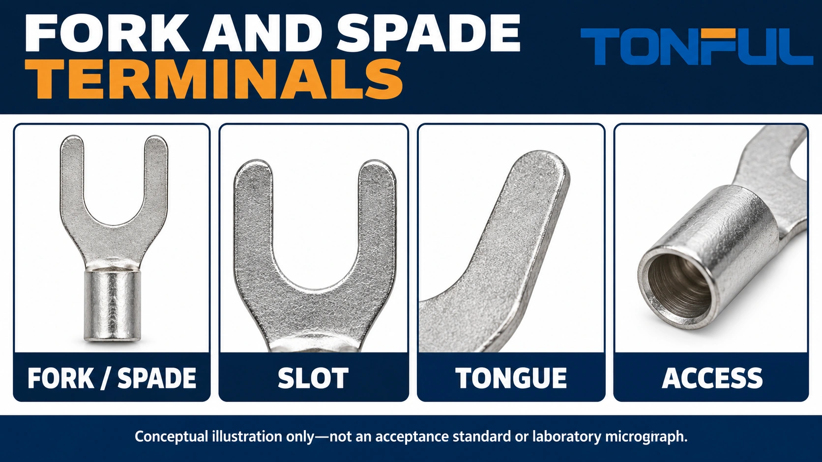
Fork and spade terminals connect a conductor to a permitted screw or stud connection through an open-sided tongue. The opening can allow installation under a loosened fastener without completely removing it, but only when the equipment geometry and instructions permit that approach. Choosing a fork solely because the slot appears to fit the stud leaves important questions unanswered.
In this guide, spade means the U-shaped fork form. Some catalogs also use spade for flat-blade quick disconnects, which have a different mating interface. Confirm the drawing before ordering. The following selection method addresses forks for clamped stud or screw connections, including their wire barrel, supported tongue area and required installation access.
Jump to: Define the interface | Stud geometry | Wire and tool | Installed access | Review record | Sourcing
Define the Fork and Spade Terminal Interface
Confirm that the equipment allows a fork
Begin with the equipment connection instruction. Determine whether it accepts a fork, requires a ring, permits a bare conductor or specifies another termination. An accessible screw head does not prove fork compatibility. Captive washers, barriers and pressure plates can change the permitted approach or prevent a fork from seating correctly.
TE Connectivity’s ring and spade overview provides a primary-source terminology reference for the open spade and closed ring forms. That distinction is useful when discussing service access, but it does not authorize a particular terminal on another manufacturer’s equipment. Keep the equipment instruction as the controlling source for the connection point.
Separate the two ends of the part
The tongue attaches to the equipment; the barrel attaches to the wire. Selecting one end does not qualify the other. Record both the wire range and the stud-interface designation, then obtain the drawing that connects those descriptions to actual dimensions. A supplier may offer several tongue widths or barrel constructions for an apparently similar nominal size.
Use TONFUL’s wire-terminal sourcing information to identify candidate families. Ask for a fork drawing rather than sending only the word spade. Include a photo or drawing of the equipment terminal so the supplier can distinguish a U-shaped stud termination from a female receptacle intended for a flat tab.
Treat maintenance convenience as conditional
A fork can simplify a permitted removal operation, but this benefit depends on having lateral access after the equipment is assembled. If neighboring wires or barriers block the opening, a fork may not be easier to service than a ring. Evaluate the installed arrangement rather than assuming a catalog silhouette predicts maintenance time.
Review Stud Fit and Tongue Geometry
Check the slot, not just the nominal stud label
Compare the fork opening and seat geometry with the actual fastener arrangement using the part and equipment drawings. Confirm the specified dimensions and tolerances. A nominal stud designation is an ordering reference, not a substitute for checking the slot opening, internal seat, tongue width and material thickness.
Do not file the slot wider or bend the tines to pass around a stud. Such changes alter the supplied geometry and can affect support under the clamping surface. If the candidate does not seat without modification, stop the selection review and request another part or an approved engineering change.
| Geometry item | What to compare | Why it matters |
|---|---|---|
| Slot opening | Fork drawing and actual fastener access | Determines whether lateral insertion is possible |
| Internal seat | Fork profile and stud or screw geometry | Determines final seating position |
| Tongue width | Contact pad, washer or pressure plate | Confirms intended support and clamping footprint |
| Tongue thickness | Hardware travel and permitted stack | Checks the assembly can clamp as intended |
| Tongue-to-barrel transition | Barrier position and fastener tool space | Prevents the barrel from obstructing seating |
| Overall length | Wire routing and neighboring components | Checks the finished installed envelope |
Review the clamping footprint
The fork must rest on the intended conductive surface and be clamped in the arrangement specified by the equipment maker. Check that neither tine rides on a shoulder or barrier. Also confirm that the barrel transition does not hold the tongue away from its seat. A fork that slides under the screw can still be poorly supported once tightened.
Use the specified hardware, tightening method and torque source. Do not apply a generic torque based only on stud diameter or terminal color. A terminal guide cannot determine the requirements of every equipment connection. If multiple terminals are proposed under one fastener, obtain explicit approval for their arrangement and stack height.

Match the Wire Barrel and Tool
Record the actual wire construction
Specify conductor material, nominal area, strand construction and insulation outside diameter. Use the wire document rather than estimating conductor size from the jacket. A nominal AWG or metric designation alone may not identify every compatible construction. If a proposed substitute wire differs in strand class or jacket dimensions, send it through the application review.
Confirm strip length and insertion against the terminal instruction. The conductor must enter the intended barrel region without discarded strands or jacket trapped in the conductor crimp. Do not trim strands to make an oversized wire fit, double back a small wire to fill a barrel, or combine conductors unless the terminal and approved engineering documents specifically permit that combination.
Select insulation by its actual coverage
TONFUL’s nylon-insulated terminal category can support a shortlist where a pre-applied sleeve is wanted. Confirm the sleeve geometry, jacket fit and covered surfaces for the exact fork. The exposed tongue and fastener still require an appropriate assembly protection plan. Standard insulation does not by itself establish moisture sealing.
For equipment with a separately specified protection arrangement, review the non-insulated terminal category. Document any boot, enclosure barrier or later-applied insulation as part of the assembly. Do not assume a bare and insulated part use identical barrels or interchangeable dies merely because their tongues look alike.
Identify the complete tooling setup
Record tool model, cavity or die, locator if required, orientation and the specified operation sequence. TONFUL’s crimping-tool range is a useful discussion point, but a broad tool range is not a compatibility approval. Request the instruction for the actual terminal and wire combination.
For production, maintain tool condition and the required verification records. A completed ratchet stroke does not prove that the right component was loaded. Check setup identity before interpreting the finished crimp. Keep process instructions separate for different barrel constructions, even when operators use the same generic name for all fork terminals.
Check Installed Access and Retention
Reserve lateral insertion space
Review the direction from which the fork enters the connection. Include barriers, adjacent poles, labels, wire supports and the fastener tool. The opening must have a usable path during both installation and service. An assembly sequence that fits an exposed bench connection may no longer work after a cover or neighboring component is installed.
Allow room for the wire to leave the barrel without forcing the tongue sideways. Where a wire bundle is restrained, verify that its installed position does not pull the fork toward the open side. Routing and support are design responsibilities; the terminal sleeve should not be treated as a substitute for the required harness restraint.
Understand the open-side tradeoff
Compared with a closed ring, a fork leaves a potential lateral escape path if the clamping arrangement is loosened. This is a geometric distinction, not a claim of a measured failure rate. A properly specified equipment connection may permit a fork, while another may require a ring or a different terminal style. Follow that permission rather than ranking one form as universally safer.
Some fork designs include formed ends or other retention features. Confirm their exact geometry and intended installation method in the supplier documentation. Do not assume they create positive locking or permit operation with a loose fastener. A visual resemblance to a locking feature is not evidence of its function.
Keep servicing outside energized work
Carry out fitting, loosening and inspection only under an approved safe-isolation procedure, with stored energy controlled and the deenergized condition verified by qualified personnel. Do not use the fork’s convenient removal geometry to disconnect a live circuit. For safety-critical equipment, including restraint or traction circuits, use the equipment-specific approved repair method rather than substituting a generic fork.
Use a Fork Terminal Review Record
Capture reasons for acceptance and rejection
The following table is an editorial selection record. Populate it with actual evidence and responsible reviewers; it is not a qualification result. A rejected candidate can remain in the file with the specific incompatibility recorded, reducing the risk that purchasing later reintroduces it as a visually similar alternative.
| Review field | Evidence to record | Hold point |
|---|---|---|
| Equipment permission | Instruction naming permitted termination form | Fork not clearly permitted |
| Slot and seat | Drawing references and reviewed dimensions | Modification needed for insertion |
| Tongue support | Contact footprint and hardware arrangement | Tine or transition not supported |
| Wire and barrel | Wire part and application instruction | Construction or jacket not covered |
| Tooling | Tool/cavity and setup instruction | Generic tool claim only |
| Installed access | Assembly drawing or trial-fit record | Lateral path or tool approach blocked |
| Protection | Guarding and insulation arrangement | Exposed surfaces not addressed |
| Release | Approved revision and engineering owner | Open substitution or deviation |

Verify the proposed assembly
Trial the intended wire, terminal, tooling and equipment interface together. Define any visual, dimensional, mechanical or electrical verification under the applicable plan, including the source of acceptance criteria. Do not substitute a universal pull force or crimp-height target from another family. Record the sample and process identities so results can be connected to the released configuration.
If service access drives the choice, review the actual removal and restoration sequence on safely isolated representative equipment. Confirm that protection can be restored and the specified hardware can be reused or replaced as instructed. This operational review provides more useful evidence than an unsupported claim that fork terminals are always faster to maintain.
Prepare the TONFUL Selection Request
Send TONFUL the wire specification, proposed fork dimensions, equipment instruction and installed-space drawing. State whether the project is new production or an approved service replacement. Include tooling availability and required documentation so the inquiry covers the whole assembly rather than just a bag of nominal stud-size terminals.
For the alternative geometry, compare the existing ring-terminal selection information when the equipment requires closed-eye capture or lateral access is unavailable. Ask TONFUL to recommend candidates for the permitted interface and provide the drawing and tooling information needed for your review. Release the chosen fork only after its wire fit, clamping footprint and service path have all been resolved.