
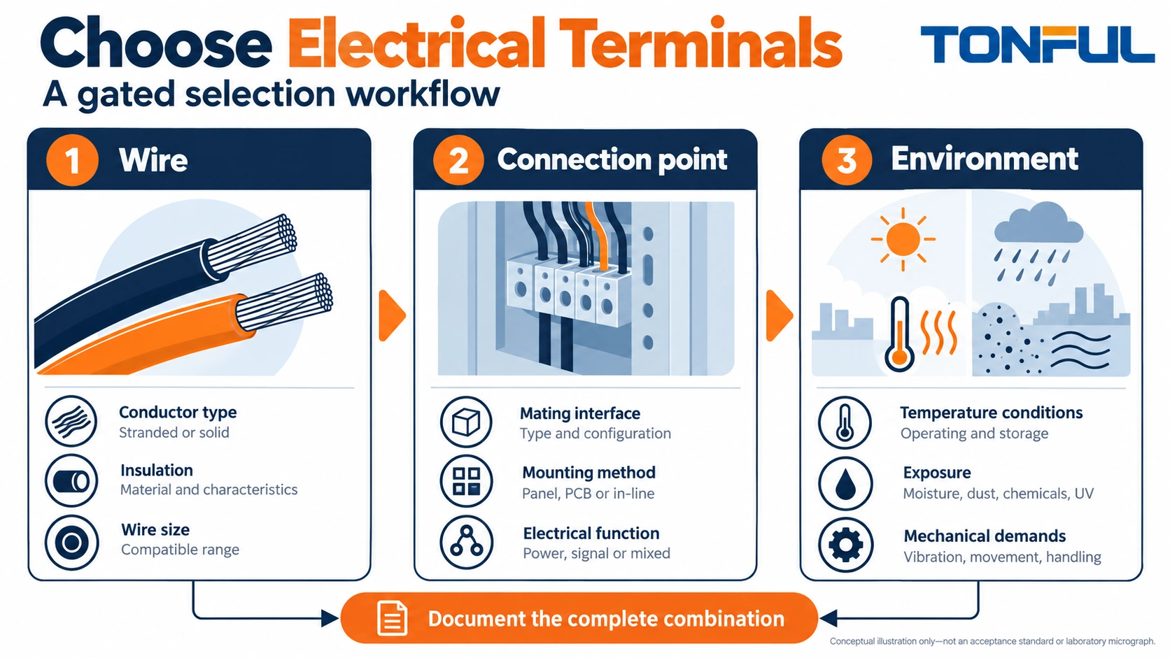
Learning how to choose electrical terminals starts with three independent questions: what conductor must be terminated, what connection point receives it, and what conditions surround the completed assembly? A familiar color or a terminal that slides onto a stud answers only part of the problem. The assembly method and supporting evidence must also match.
Use the following gated workflow before requesting samples. Each gate produces an input for the next one, and an unresolved compatibility question stops selection rather than becoming an assumption in the purchase order. The result is a complete specification that purchasing, assembly and quality teams can use together.
Jump to: Conductor · Connection point · Environment · Assembly · Evidence · RFQ
How to Choose Electrical Terminals: Start With the Conductor
Record more than nominal wire size
Identify conductor material, AWG or square-millimeter size, strand construction, conductor plating where relevant and insulation outside diameter. A terminal’s wire range is not a generic permission to use every conductor with that nominal size. The selected product’s application documentation must cover the actual wire construction.
Do not choose from the cable jacket diameter. Two wires can share an outside diameter but contain different conductor areas, and two equal-area wires can have different insulation thicknesses. The metal barrel and insulation support need separate compatibility checks.
Color is useful for identification within a controlled family, not as a universal technical specification. A red or blue sleeve cannot identify the stud hole, barrel construction, insulation diameter range or correct die. Put the exact part number and conductor specification on the selection record.
| Conductor input | Why the buyer needs it | Question to resolve |
|---|---|---|
| Material | Determines compatible contact and termination system | Is this exact conductor material permitted? |
| Nominal area | Screens the documented wire range | Does the selected range cover the wire? |
| Strand construction | Affects packing and preparation | Is the actual construction supported? |
| Insulation diameter | Controls entry and support fit | Does the sleeve accept the jacket without damage? |
| Number of conductors | Changes the termination combination | Is that combination explicitly approved? |
Keep multiple conductors as a separate decision
Do not combine two wires in a barrel merely because their areas appear to fit. Ask for a supported combination and the associated tooling and preparation instructions. If the terminal does not support it, engineering may choose a branch component or a separate connection point.
For panel wiring, TONFUL’s cord end terminal range distinguishes single and twin ferrules. A twin ferrule also needs receiving-terminal permission for that arrangement. It is not a workaround for a terminal block that prohibits the proposed conductor combination.
Match the Actual Equipment Connection Point
Choose the interface before the sleeve material
For a stud attachment, compare the stud designation, opening geometry, tongue dimensions and hardware arrangement. A closed ring eye and an open fork slot offer different assembly and removal behavior. The equipment instruction determines whether either form is permitted and how it is fastened.
For a blade connection, specify both tab width and thickness, plus the mating features and orientation. A receptacle that fits over a blade is not automatically a compatible mating part. Contact geometry, retention features, material and finish can matter even when the nominal width matches.
For a screw or spring terminal that receives a conductor end, confirm whether bare wire, a ferrule or a specified pin terminal is allowed. Check permitted conductor ranges with the chosen preparation. Do not assume a ferrule increases the terminal’s capacity or makes every fine-stranded wire acceptable.
Check installed and service space
Include overall length, tongue width, insulated envelope, wire exit direction and available bend space. Also check fastener-tool access, latch movement or receptacle removal clearance. An assembly can fit the enclosure and still be impossible to service without damaging adjacent wiring.
Consider how the connection will be replaced. A terminal that requires removing a stud nut may be appropriate for retained attachment but less convenient for frequent module replacement. A separable connector may suit that service task better, provided its application and mating requirements are satisfied.
TONFUL’s non-insulated terminal category can help identify available terminal shapes for a drawing-level discussion. Use it as a product-family reference, not as evidence that a visually similar form is an approved equipment substitute.

Define the Environment and Protection Boundary
Describe exposure at the installed location
Write down temperature exposure, moisture, condensation, chemicals, vibration, cable motion and possible contact with adjacent conductive surfaces. Distinguish normal operation from cleaning, storage and service. “Indoor” does not necessarily mean dry, cool or free of chemical exposure.
Choose protection for the whole connection. A pre-insulated barrel is not automatically a sealed wire entry. A ring terminal’s sleeve may cover the conductor barrel while leaving the tongue exposed. A non-insulated part may be suitable within a correctly designed enclosure, but the enclosure and spacing remain part of the safety strategy.
If sealing is needed, request a system with documented application scope rather than adding tape or tubing and calling the result waterproof. The wire insulation, sealing material, installation method and installed condition all affect the protection claim. A component name does not establish an ingress classification.
Evaluate the exact insulation construction
PVC, nylon and heat-shrink constructions should be compared as finished parts, not as broad polymer rankings. Grade, dimensions, metal support, application tooling and part-level limits can differ. A polymer’s general material description does not establish the terminal’s complete temperature or voltage suitability.
The nylon-insulated terminal category is a useful starting point when that family fits the application. Request the selected part’s insulation diameter range and application documentation. Do not assume that a transparent sleeve proves crimp quality or that nylon insulation creates a sealed assembly.
Set a safe-work boundary
Installation and replacement should occur on isolated equipment under the applicable site procedure. OSHA 1910.333 addresses US electrical work practices and deenergization responsibilities. This selection guide does not authorize live-circuit repairs or generic substitutions in traction-battery, restraint, medical or other safety-related systems. Those applications require the responsible equipment authority’s approved components and procedures.
Confirm That Production Can Control the Assembly
Select the terminal and tool together
Before approving a terminal, identify how it will be stripped, loaded, crimped and inspected. Record the specified tool, cavity or applicator and any locator or setup requirement. Tool compatibility belongs to the exact conductor-terminal combination, not merely a broad wire-gauge label.
Ask TONFUL’s crimping-tool team to identify the tooling basis for the proposed part. Provide the wire construction and insulation diameter. A recommendation that omits those details needs clarification before production release.
Consider access during assembly. A terminal may require a crimp orientation or tool approach that becomes difficult after another component is installed. Plan the assembly sequence rather than expecting operators to bend the terminal or alter the wire preparation to gain access.
Define checks before making volume parts
Establish a first-piece review covering wire identity, stripping condition, full insertion, crimp placement and finished fit. The control plan should identify when a new check is required after material, tooling, setup or restart changes. Keep acceptance criteria tied to the relevant drawing or application specification.
A visual inspection can detect escaped strands, split barrels, displaced insulation and gross deformation. It does not establish all mechanical, electrical or environmental performance. If the application requires verification tests, engineering must define the method, samples, conditions and acceptance source. Do not borrow universal pull-force or resistance limits from an unrelated terminal family.
For screw-fastened interfaces, add the equipment’s hardware and tightening requirements. For blade interfaces, add full mating and retention checks as specified. The conductor crimp and equipment attachment are separate release decisions; a good result at one end does not prove the other.
Evaluate Documentation and Alternatives Without Assuming Equivalence
Ask what the evidence actually covers
Request the part drawing, application instructions, material information and relevant approval or test documentation for the proposed configuration. Check the exact part number, conductor range, product revision and installation conditions covered. A report for another size or construction is not automatic evidence for the requested part.
Distinguish a supplier quality-system certificate from a component approval and a finished-assembly qualification. A logo on a marketing page cannot establish all three. Where evidence is not available, record the gap for engineering review instead of converting a sales statement into a compliance claim.
| Proposed change | Compatibility review required | Evidence to retain |
|---|---|---|
| Same shape, different wire range | Conductor and insulation fit | Drawing and supported wire data |
| Same stud size, wider tongue | Seating, clearance and hardware | Interface layout and sample review |
| Same tab width, different thickness | Exact mating pair | Mating drawings and application data |
| Different insulation construction | Tooling, protection and exposure | Part-level instructions and verification plan |
| New tool or die | Formed termination and process controls | Approved setup and verification record |
Compare total installed effort
Compare piece price only after the technical boundary is the same. Include separate sleeves, housings or hardware, tooling investment, assembly operations, inspection access and expected service procedure. These are cost-model inputs, not claims that one terminal form always has a lower failure rate or labor cost.
Ask suppliers to list deviations explicitly. A quotation marked “equivalent” should identify what is unchanged and what differs. Purchasing should not accept a hidden material, barrel or insulation change solely because the sample fits the equipment stud.
Turn the Selection Into an RFQ and Release Record
Send a compact but complete specification
Use one line per connection point. Include the circuit or assembly reference so the supplier can distinguish similar terminals used at different locations. Attach a drawing when the interface is not obvious from a standard designation.
| RFQ section | Required information |
|---|---|
| Wire | Material, size, strand construction, insulation diameter |
| Connection | Stud or tab dimensions, receiving equipment, orientation |
| Environment | Exposure and protection requirements |
| Assembly | Tooling, production method and service access |
| Evidence | Drawings, application instructions and required qualification scope |
| Supply | Part identification, packaging, lot traceability and change control |
Request representative samples before volume release where the development plan calls for fit or process review. Identify the samples and retain the disposition. A sample demonstration helps resolve installation questions but does not replace required qualification or establish production consistency by itself.

Close the selection with TONFUL
Share the completed record with TONFUL’s wire-terminal sourcing team. Ask for an exact part recommendation, controlled dimensions and compatible tooling references, with any unresolved application limitations stated clearly. Release the choice only when wire fit, equipment interface, protection and assembly controls agree. That sequence makes the terminal specification useful to every team that must purchase, assemble, inspect or replace it.