
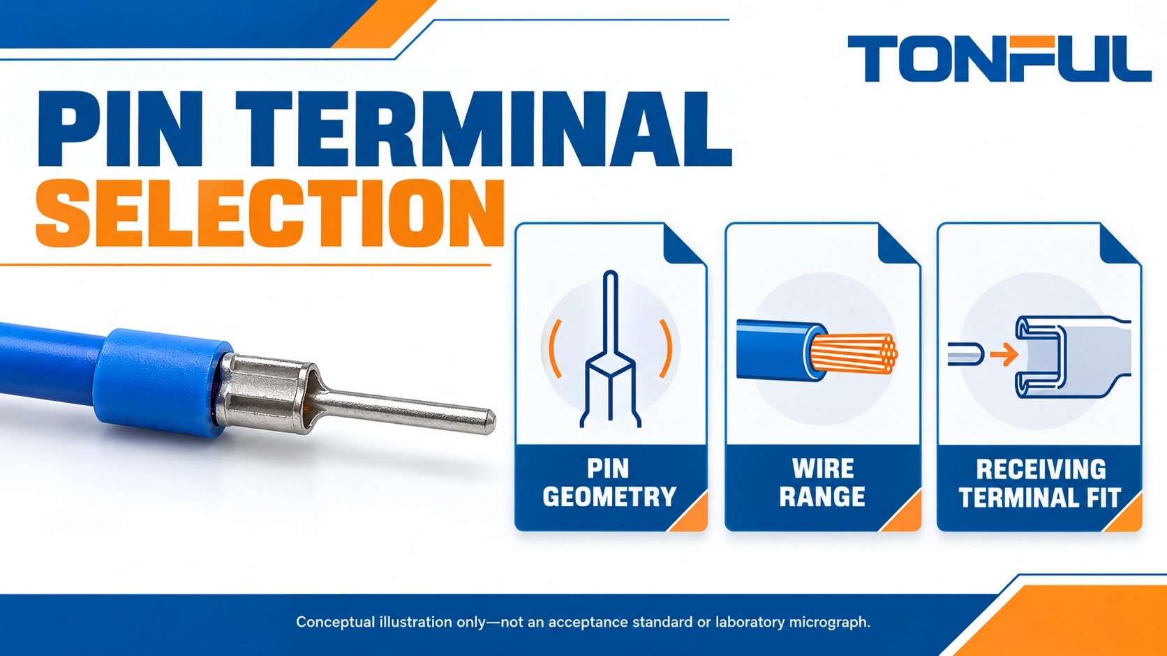
Pin terminal selection starts at the receiving connection, not at the wire barrel. The pin must have an approved shape, section and insertion length for the clamp or socket, while the barrel must suit the actual conductor and termination process. A pin that enters an opening can still be unsuitable for the contact system behind it.
This guide addresses crimp-on wire pin terminals used to terminate a conductor into a compatible receiving terminal. It does not cover PCB press-fit pins, loose electronic header contacts or every contact described as a pin. Use the fit record below to connect the receiving equipment drawing, selected wire and proposed terminal before ordering production quantities.
Jump to: Identify the pin interface | Pin dimensions and engagement | Wire range and barrel fit | Crimp process and inspection | Application fit record | Purchase and change control
Identify the Pin Interface
Separate wire pins from ferrules
A wire pin terminal provides a defined projecting contact form attached to a crimp barrel. A ferrule generally consolidates stranded wire inside a sleeve, with the crimped sleeve entering an approved clamp. They should not be substituted on appearance alone. The equipment manufacturer’s permitted conductor and termination list decides which form can be used.
Review the TONFUL cord end terminal range when the receiving terminal specifies ferrules, rather than assuming that a pin terminal is an equivalent. Conversely, do not replace a specified pin with a ferrule merely because both fit through the front opening. Clamp geometry and contact engagement can depend on the intended termination.
The official TE wire pin product page lists mating pin dimensions, conductor range and insulation diameter as separate characteristics and directs design work to the product drawing. That distinction is useful here; its particular values are not a specification for TONFUL products or evidence of interchangeability.
Obtain the receiving terminal’s instructions
Record the receiving component part number, revision and manufacturer instructions. Identify the permitted conductor preparation, termination type, insertion depth and tightening or operating method. If the documentation only approves bare wire, do not infer approval for a pin. Obtain the equipment owner’s engineering decision or choose an explicitly supported termination.
Ask whether a socket is intended for a matching contact family or whether a clamp accepts a range of termination forms. A spring socket designed for a specific male contact is not a generic terminal-block opening. Retention, contact pressure and insulation coordination need to be considered within the actual system, not guessed from an opening diameter.
Pin Dimensions and Engagement
Check the complete shape
Pin diameter is meaningful for a round section; a flat or rectangular pin also needs width, thickness and orientation. Record the actual section rather than collapsing every form into a nominal “pin size.” Include corner form, transition geometry and finish where the receiving specification makes them relevant. Never force an oversized pin into a clamp to make it fit.
Insertion length is the usable projecting portion, not the overall terminal length. A long barrel or insulation sleeve does not increase engagement inside the receiving terminal. Conversely, a pin that is too long may bottom out before its intended seating position or expose conductive material outside the protected region. Use the specified engagement and enclosure limits.
| Fit characteristic | What to compare | Stop condition |
|---|---|---|
| Pin section | Diameter or width and thickness, with tolerances | Shape not permitted by receiving instructions |
| Usable pin length | Required insertion and contact zone | Bottoming or insufficient engagement |
| Transition and shoulder | Entry aperture and seating position | Shoulder prevents intended insertion |
| Sleeve envelope | Adjacent poles and access space | Insulation prevents seating or obstructs operation |
| Contact finish | Approved material pairing | Unreviewed finish substitution |
| Installed clearance | Exposed metal and neighboring parts | Protection requirements not established |
Consider tolerance combinations
Compare the permitted terminal and receiving-part limits, not just nominal dimensions. If the drawing leaves the functional pin section ambiguous, request clarification before buying. A successful fit with one sample does not resolve the limits of a broad tolerance stack. Engineering should decide which configurations need dimensional or assembly evaluation.
Keep insertion alignment separate from wire routing. The pin should enter along the permitted axis without being used as a lever to move the wire into place. Provide adequate support and access for the actual terminal operation. A cable tie pulling the barrel sideways can change the installed load even when the original loose sample fit correctly.

Wire Range and Barrel Fit
Describe the actual conductor
Record nominal cross-section or AWG, conductor material, strand construction, plating where relevant and insulation diameter. The selected terminal must be approved for that construction. Do not assume that a published range covers every fine-stranded, solid or unusually insulated wire of the same nominal size.
The conductor barrel and insulation support perform different jobs. The conductor crimp establishes the intended mechanical and electrical connection; the insulation support controls the wire where the design provides it. An insulation sleeve fitting over the jacket does not prove that the conductor fits the metal barrel. Keep both checks in the selection record.
Use non-insulated terminal options where the assembly provides the required insulation and protection elsewhere. Review nylon-insulated terminal options where covered construction is relevant. Neither category alone establishes the rating or suitability of a particular pin terminal; request the exact part drawing and application information.
Do not improvise the wire population
One wire is not automatically interchangeable with two smaller wires, even if their nominal areas add to the same total. Barrel fill, strand distribution and insulation support differ. Use a multi-wire arrangement only when the exact combination and process are authorized. Do not fold the conductor to fill a large barrel unless the applicable instruction explicitly permits that preparation.
If several approved wire sources will feed production, list them separately and assess the need for additional validation. Purchasing should not substitute wire based on nominal area alone after engineering has selected a terminal. Record whether changes in strand count, insulation diameter or conductor finish trigger renewed review.
Crimp Process and Inspection
Match the complete termination system
Select the terminal, wire, tool, die, cavity and locator as a documented combination. Identify the applicable strip length and setup instruction from the supplier’s approved information. Do not use a ferrule crimper, universal pliers or a color-coded cavity as proof that the required pin terminal crimp has been achieved.
Discuss the exact configuration when reviewing TONFUL crimping tools. Ask whether the proposed tool controls the barrel shape while preserving pin alignment and the transition region. A deformed pin may pass a wire pull evaluation while failing the receiving interface, so preserve the functional geometry as an independent check.
Inspect before the pin disappears into the clamp
Check wire preparation for damaged or missing strands and insulation in the conductor crimp area. Check conductor insertion, barrel closure and insulation support against the applicable criteria. Inspect the pin for bending, twisting, plating damage and tool marks in the functional contact region. Confirm that the intended pin length remains available after crimping.
When testing is required, define sample quantity, mechanical fixture, equipment range and accuracy, conditioning, speed, invalid-test handling and acceptance-source revision before testing. Do not substitute a hand tug for specified validation. Receiving-terminal engagement and clamp operation may need a separate assembly evaluation; a pull test on the wire barrel does not cover every interface failure mode.
Application Fit Record
Complete one record per released configuration
Use the following blank template as an engineering handover, not as a claim that tests have passed. Link each result to an evidence file and reviewer. Mark unknowns unresolved. Avoid green checkmarks that conceal whether the decision came from a drawing, actual inspection or an assumption.
| Record field | Required entry | Evidence owner |
|---|---|---|
| Receiving terminal | Part, revision and permitted termination | Equipment engineer |
| Pin terminal | Supplier part and drawing revision | Component engineer |
| Pin geometry | Section, usable length and tolerance comparison | Mechanical reviewer |
| Wire | Exact identity and construction | Harness engineer |
| Tool system | Tool, die, cavity and instruction revision | Manufacturing engineer |
| Insulation and clearance | Installed enclosure and adjacent-pole review | System engineer |
| Validation | Plan, samples, results and acceptance document | Quality engineer |
| Release | Restrictions, signatories and change triggers | Design authority |

Evaluate the installed condition
For a terminal block, follow its prescribed operation and torque where applicable; do not invent a tightening value from wire size. Confirm that the conductive part is in the intended contact zone and that the insulation is not trapped in it. Check access after covers, adjacent conductors and labels are installed, not just on an empty bench.
Consider vibration, repeated service, moisture exposure and temperature within the system’s requirements. A pin sleeve is not an environmental seal, and a component rating is not the assembled equipment rating. Where wires move, evaluate routing and strain relief rather than asking the contact to absorb repeated bending at the barrel exit.
Purchase and Change Control
Buy the approved identity
Send the supplier the fit record and receiving-interface requirements when requesting samples. Require the quoted terminal drawing, wire range, compatible tooling and packaging format. Separate a supplier-proposed alternative from an already approved item. Similar photos and catalog color do not establish the same functional geometry.
Link incoming packages to the approved supplier part and revision. Define lot identification and handling so pins are not bent during storage or feeding. If production operators straighten a pin to obtain fit, stop and investigate the configuration rather than normalizing an uncontrolled repair. Retain the affected lot and evidence for review.
For sample handover, include the receiving component or its controlled interface extract, a retained wire sample, the proposed pin drawing and the tooling instruction. Label the intended assembly orientation. These four references let the reviewer distinguish a pin-fit problem from a wire-preparation or barrel-process problem without guessing which item changed between trials.
Keep field work within authorized boundaries
Install or inspect only on safely de-energized equipment using the site’s isolation procedures and authorized personnel. Do not remove covers or test engagement on a live terminal. Safety-related machinery functions, traction equipment and regulated assemblies require their own approved modification process; this selection guide does not authorize substitutions.
For a TONFUL sourcing discussion, share the receiving terminal instructions, pin geometry, wire construction and tooling plan. Ask the wire terminal team for the proposed part drawing and documented exceptions, then release the exact configuration through your engineering process before ordering production quantities.