
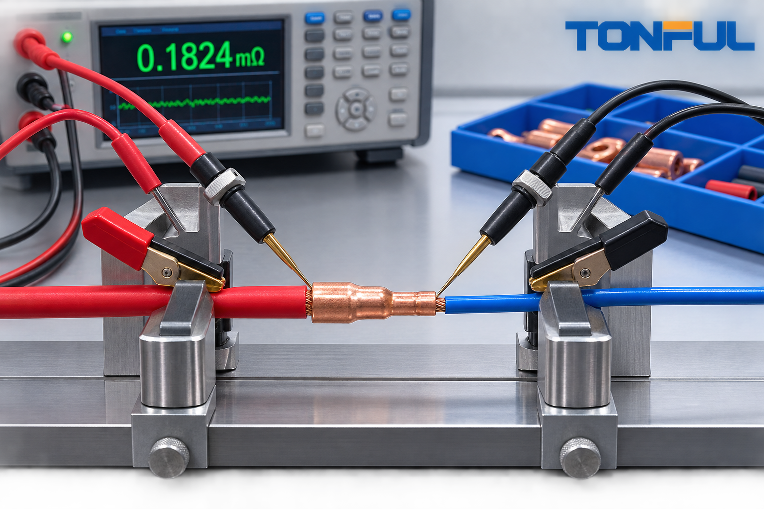

A step-down butt splice has two different crimp interfaces. The large side and small side may use different conductor sizes, barrel dimensions, die cavities, and process windows. Testing only the complete assembly can hide which end caused a failure. A reliable control plan evaluates each end separately and then verifies the finished electrical path.
Do not copy universal acceptance numbers from a blog. Pull force, crimp height, and resistance limits must come from the applicable terminal specification, wire construction, customer requirement, and approved validation plan.
Start with a Controlled Test Plan
Define the test purpose before making samples: design qualification, first-article approval, process setup, periodic verification, change validation, or failure analysis. Record connector lot, wire manufacturer and lot, conductor size, strip length, tool ID, die ID, cavity, setting, operator, and date. Condition the tool and make samples using the same process planned for production.
Do not invent a universal sample quantity. Enter the quantity required by the product drawing, customer specification, applicable standard, or approved qualification plan. If none exists, engineering must approve a statistically and technically justified plan before testing.
| Test-plan field | Required entry |
|---|---|
| Test purpose | Qualification, first article, verification, change, or investigation |
| Sample quantity per end | Fill from controlling document; do not use a generic value |
| Sample grouping | Connector lot, wire lot, tool/cavity, operator, and condition |
| Preconditioning | Temperature/humidity conditioning, stabilization time, or “not required,” with source |
| Acceptance source | Product drawing, application specification, customer document, standard, or approved plan |
| Retest rule | Define whether retest is allowed, who authorizes it, and how original failures remain reported |
| Invalid-test rule | Define fixture slip, specimen damage, machine error, or setup deviation and disposition |
TONFUL’s wire harness manufacturing process explains why traceability must connect materials, tooling, and inspection.
1. Visual and Dimensional Inspection
Before destructive testing, inspect:
- Full conductor insertion on both sides
- No cut, missing, folded, or escaped strands
- Correct insulation clearance
- No barrel cracks or severe deformation
- Correct crimp location and orientation
- Acceptable bellmouth where specified
Measure each barrel’s crimp height at the location and orientation defined by the terminal supplier. A step-down splice normally requires two nominal values, not one shared value.

Use a calibrated crimp micrometer or the specified measurement system. Do not substitute overall sleeve width for conductor crimp height.
For every reading, record the small or large end, measurement location, instrument ID, resolution, result, lower and upper limits, acceptance-source document and revision, inspector, and date. If the product drawing does not provide a crimp-height window, do not create one from a visually acceptable sample.
2. Pull Force Testing
Test the small-wire termination and large-wire termination as separate populations. Before testing, complete these controlled fields:
- Sample quantity for each end
- Required tensile speed from the controlling document
- Grip and fixture method
- Pull direction and specimen free length
- Pull-tester range, resolution, and accuracy
- Instrument calibration status
- Conditioning or stabilization requirements
- Minimum force or other acceptance criterion for each end
- Acceptance-source document and revision
Select equipment so the expected result falls within an appropriate validated part of its measurement range. Clamp the terminal without crushing or loading the conductor crimp, secure the wire without damaging it, align the pull with the wire axis, and use the speed required by the controlling specification.
The official Molex Quality Crimp Handbook describes controlled sample preparation, clamping, and pull testing, including a handbook procedure with a defined speed. Do not automatically transfer that example speed to a TONFUL product or customer program; enter the value required by the applicable test document.
Record peak force and failure mode for every valid specimen. Wire breakage, conductor pullout, barrel fracture, or another specimen failure mode do not mean the same thing. Fixture slip, grip damage outside the defined acceptance condition, machine overload, or a setup deviation may make a test invalid rather than failed; retain the original record, document the reason, correct the setup, and repeat only under the approved invalid-test or retest rule. Never delete an inconvenient result or replace a failed specimen without authorization.
The small and large ends can have different acceptance minima because they use different conductors and crimp interfaces. Record the source for each end rather than applying the larger-wire limit to both.
TONFUL’s crimp pull-force testing guide provides additional production context.
3. Electrical Resistance Testing

Use a low-resistance measurement method and a repeatable fixture. A four-wire Kelvin method is often useful when the expected resistance is small, but the approved procedure must define the complete setup.
Record these fields before measurement:
- Test current and current direction
- Whether forward/reverse readings or instrument offset compensation are required
- Force-lead and sense-probe positions on both sides
- Reference length of conductor included in the measurement
- Wire size, material, strand construction, and temperature
- Ambient and stabilized specimen temperature
- Instrument range, resolution, accuracy, zeroing, and calibration status
- Whether an equal-length wire baseline is measured and subtracted
- Initial resistance acceptance limit
- Post-aging resistance limit or permitted change from initial value
- Acceptance-source document and revision
Place Force and Sense contacts consistently so changes in lead spacing do not masquerade as splice variation. If the method includes conductor resistance, maintain the same reference length for every sample. If the approved method requires subtracting the resistance of equivalent wire lengths, record the baseline and calculation; otherwise report the complete measured path without an undocumented correction.
Where offset compensation is required, use the instrument’s approved method or take defined forward and reverse measurements. Do not improvise a correction after seeing the result.
Test baseline samples and, where required, repeat after thermal cycling, vibration, humidity, salt exposure, or current loading. Record the initial value, aged value, absolute change, percentage change when specified, and pass/fail result. Control specimen temperature because copper resistance varies with temperature.
TONFUL’s wire harness continuity testing guide explains why continuity alone does not characterize a low-resistance connection.
4. Cross-Section and Process Capability
Cross-section selected samples when required by the qualification plan, product specification, customer requirement, process-development plan, or investigation. Evaluate strand compaction, symmetry, voids, barrel closure, and damage. Use the terminal supplier’s criteria; a polished image is not a pass/fail standard by itself.
Once limits are approved, track crimp height and other critical variables statistically. Pull tests validate mechanical performance but are destructive and cannot replace ongoing dimensional control.
Minimum Validation Matrix
| Check | Small end | Large end | Complete splice |
|---|---|---|---|
| Visual inspection | Required for process release and production acceptance as specified | Required for process release and production acceptance as specified | Verify complete assembly as specified |
| Crimp height | Required when defined by the terminal or process specification | Required when defined by the terminal or process specification | Not normally an assembly-level measurement |
| Pull force | Required when specified; use small-end limit and source | Required when specified; use large-end limit and source | Assembly test only when specified |
| Resistance | Included in the complete-path setup as defined | Included in the complete-path setup as defined | Required when specified by the qualification plan, product specification, or customer requirement |
| Cross-section | Required when specified by the qualification plan, product specification, or customer requirement | Required when specified by the qualification plan, product specification, or customer requirement | As defined by the sectioning plan |
| Environmental conditioning | Apply to this interface when specified | Apply to this interface when specified | Required when specified by the qualification plan, product specification, or customer requirement |
Use TONFUL’s crimping tool calibration guide to connect tool verification to test results.
Step-Down Butt Splice Test Record Template
Use one row per measured end or specimen. Add separate columns for initial and aged resistance when the qualification plan requires environmental conditioning.
| Sample ID | End | Wire construction | Tool / cavity | Crimp height result / limit | Pull result / failure mode | Resistance result | Acceptance-source document | Pass / fail | Inspector / date |
|---|---|---|---|---|---|---|---|---|---|
| ______ | Small / Large | AWG or mm2; material; plating; strand count; insulation | Tool ID; die; cavity; setting | Result; lower/upper limit; instrument ID | Peak force; minimum; failure mode; valid/invalid | Initial; aged; change; unit; baseline treatment | Document number; clause; revision | ______ | ______ |
| ______ | Small / Large | ______ | ______ | ______ | ______ | ______ | ______ | ______ | ______ |
| ______ | Small / Large | ______ | ______ | ______ | ______ | ______ | ______ | ______ | ______ |
Attach the raw machine file, resistance setup diagram, probe-spacing record, environmental exposure record, cross-section images where required, and any invalid-test or retest authorization.
Build Limits from Evidence
The strongest plan links every acceptance limit to a drawing, application specification, customer requirement, or qualification report. Share both wire constructions, connector drawing, tooling, and end-use environment with TONFUL when requesting samples or a validation plan.