
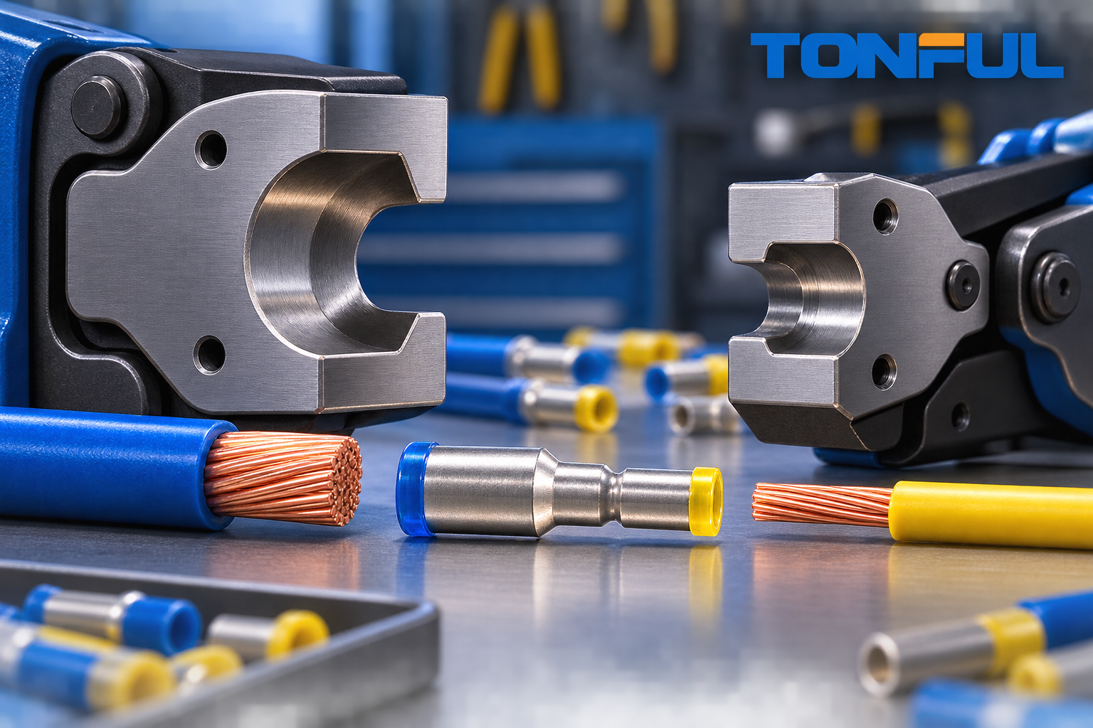
A step-down butt connector may require one die cavity for the large barrel and another for the small barrel. The correct choice comes from the connector application specification and validated wire pair, not only from insulation color or a generic AWG label on the tool.
Die selection is a process-engineering decision. The terminal, conductor, insulation, locator, cavity profile, press or hand tool, setup, measurement method, and acceptance plan form one application system. A die that closes around the connector is not necessarily a qualified die, and a satisfactory pull result alone does not establish electrical or long-term reliability.
Collect the Complete Application Inputs
Start with exact connector and wire part numbers rather than nominal families. Record the conductor material, plating, strand count, individual strand diameter where available, insulation material and outside-diameter tolerance, number of conductors per end, strip-length requirement, production volume, environment, and governing drawing or customer specification.
Two wires with the same AWG or mm² may compact differently. Fine-stranded, compact, plated, solid, or mixed-conductor constructions can change insertion and deformation. If multiple wires enter one barrel, determine effective wire size by the applicable specification and validate the exact bundle. Never choose the cavity only because the wires physically fit.
Begin with the Connector Drawing
Collect the connector part number, large- and small-end wire ranges, barrel dimensions, strip lengths, approved tool, die or applicator, cavity, crimp orientation, and nominal crimp-height requirements.
If the documentation lists only one broad range, ask whether it applies independently to both ends. Review TONFUL’s step-down butt connector guide for product terminology.
The application drawing should identify tool family, die or applicator, cavity, locator, orientation, strip length, insertion, nominal crimp height and tolerance where controlled, visual criteria, and required tests. If the drawing and tool label conflict, stop and resolve the discrepancy with the connector manufacturer. Do not average the two barrel sizes or use the nearest color-coded cavity as an engineering substitute.
| Required input | Large end | Small end | Evidence source |
|---|---|---|---|
| Barrel geometry and conductor range | Record | Record | Controlled connector drawing |
| Exact wire construction | Record | Record | Wire datasheet and sample |
| Tool/die/cavity/locator | Record | Record | Application specification |
| Strip length and orientation | Record | Record | Work instruction |
| Crimp-height window | Record | Record | Validated process data |
| Pull/resistance/cross-section requirement | Record | Record | Qualification or control plan |
Why One Cavity May Not Work for Both Ends

The large barrel needs a cavity that supports its geometry and compacts the larger conductor. The small barrel needs a smaller controlled profile. Using the large cavity on both ends can leave the small wire loose; using the small cavity on both can damage the large barrel or prevent closure.
Some engineered tools combine two suitable cavities in one die set. Others require two operations or settings. Neither arrangement is automatically better; process control and validation decide.
The cavity must support the barrel while producing the intended conductor compression without cracks, harmful flash, severe strand damage, or unstable geometry. Locator design controls axial and rotational position. Insulated and heat-shrink constructions also require support that avoids cutting, crushing, or overheating insulation. Therefore, a geometrically similar uninsulated terminal does not prove compatibility with an insulated step-down splice.
When one die set has two cavities, mark them unambiguously and prevent sequence errors. When two tools or settings are used, control work-in-process orientation and verify that an operator cannot crimp the same end twice or skip an end. Choose the arrangement by validated results, production volume, ergonomics, cycle risk, maintenance, and inspection needs.
Do Not Select by Color Alone
Red, blue, and yellow conventions can help identify broad insulated-terminal ranges, but colors vary by product system and do not define a qualified reducing-splice tool. TONFUL’s terminal color-code chart should be used as a reference, not as tooling approval.
Tool embossing can also be misleading when it lists only a general AWG range. It may refer to another barrel style, insulation system, or terminal manufacturer’s geometry. Verify tool documentation, connector approval, and exact wire samples. Avoid improvised shims, repeated partial cycles, or rotating the connector between compressions unless an approved application instruction explicitly requires that process.
Hand Tool, Press, or Applicator
| Production context | Tooling approach | Key control |
|---|---|---|
| Service or prototype | Approved ratchet hand tool | Correct cavity and full cycle |
| Low-volume production | Controlled bench tool or press | Setup, gauge, and operator method |
| High-volume production | Applicator and monitored press | Shut height, crimp height, maintenance |
| Custom connector | Dedicated or modified tooling | Qualification and ownership |
Hand tools need a full-cycle mechanism where specified, controlled cavity identification, locator condition, handle-force monitoring where appropriate, and periodic verification. Bench tools and presses add setup, guards, shut-height or stroke controls, and first-piece release. Applicators for higher volume may add feed adjustment, terminal position, crimp-force monitoring, counters, and preventive maintenance.
Select equipment that can repeatedly operate inside the validated process window. Greater force capacity does not make a hydraulic or powered tool suitable. The die profile and controlled final geometry matter more than maximum advertised force. For service use, also consider portability, calibration access, operator variability, and whether the field tool is included in the qualification scope.
Use TONFUL’s ratcheting versus hydraulic crimper guide for general tool architecture, while recognizing that a specific terminal may require a different approved system.
Two-End Work Instruction

The work instruction should state:
- Connector and wire part numbers
- Tool and die IDs
- Large-end cavity and orientation
- Small-end cavity and orientation
- Strip length and insertion method
- Crimp sequence
- Crimp-height checks for each end
- Visual criteria and sampling
- Pull and resistance test requirements
- Tool verification and maintenance interval
The official Molex Quality Crimp Handbook describes disciplined crimp setup, measurement, and pull testing.
Add photographs or diagrams showing connector orientation, which end is processed first, where each cavity contacts the barrel, measurement location, acceptable conductor brush or insertion evidence, and prohibited conditions. Use unique tool, die, cavity, and locator IDs. Operators should not have to infer a cavity from connector color.
The instruction must also define first-piece approval after shift start, tool installation, cavity change, adjustment, repair, wire or connector material change, and a specified downtime restart. State who may set, approve, adjust, and release the process. Link training authorization to the current instruction revision.
Validate Before Release
Make samples with production wire and tooling. Measure each end independently, perform separate pull tests, inspect cross-sections where required, and verify resistance across the finished splice. Repeat after tooling adjustment or material changes.
Build a Process Window
Begin at the manufacturer-approved setup and make identified samples for each end. Record tool, die, cavity, locator, machine, setting, connector lot, wire lot, operator, strip length, and environmental condition. Measure crimp height using the approved method and instrument. Explore only settings authorized by the development plan; do not damage production tooling through uncontrolled trials.
For each planned condition, examine visual quality, dimensional stability, pull-force result and failure mode, resistance where specified, and cross-section where required. Sample quantities, acceptance criteria, conditioning, pull speed, fixtures, test current, probe locations, and retest rules must come from the drawing, customer specification, qualification plan, or applicable standard. Do not invent universal values.
The selected setting should provide margin from both overcrimp and undercrimp conditions while remaining stable across expected wire, terminal, tool, machine, and operator variation. A single good sample at nominal setup is not a process window.
Validate Both Ends and the Complete Splice
Treat the small and large barrels as separate crimp interfaces. Record separate height, appearance, pull, and cross-section evidence, then evaluate resistance across the assembled splice when required. Confirm strip length and insertion so the test is not masking conductor positioned outside the intended compression zone.
Qualification should use production-intent material, tooling, operators, and work instructions. Repeat relevant evidence after changes to barrel geometry, material, plating, insulation, wire construction, die profile, locator, machine, manufacturing location, or inspection method according to the approved change plan.
TONFUL’s crimp die selection guide explains common jaw families, while the tool calibration guide covers ongoing control.
Control the Tool in Production
Tool control starts with receipt and identification. Verify die and locator part numbers, revision, condition, and compatibility before use. Store tooling to prevent impact, corrosion, contamination, and component mixing. Maintain a history of cycles or usage, cleaning, lubrication where specified, inspection, adjustment, repair, and replacement.
Use an approved master or verification method where applicable, but do not confuse tool verification with product acceptance. The production crimp still needs defined first-piece and in-process checks. Measurement instruments require suitable range and resolution, calibration traceability, status identification, and an MSA or GR&R approach for critical dimensional decisions.
SPC can help detect drift in a stable crimp-height process. Control limits describe process behavior; specification limits define product acceptance. The control plan should state sample frequency, reaction to trends or out-of-control signals, product containment boundary, setup reapproval, and escalation. Cp/Cpk or other capability evidence should be used only when appropriate and assessed against the organization’s approved criteria.
Diagnose Tooling Problems Systematically
| Symptom | Evidence to collect | Possible tooling/process causes | Immediate action |
|---|---|---|---|
| High or variable crimp height | Both-end measurements, setup, cavity history | Wear, loose die, setting, incomplete cycle | Stop and contain since last verified check |
| Low height or strand damage | Section, wire construction, cavity ID | Wrong cavity, excessive closure, oversized wire | Quarantine and verify application inputs |
| Asymmetry or flash | Section orientation, locator, die faces | Misalignment, rotation, damage, contamination | Inspect and clean tooling; reapprove setup |
| Low pull result | Failure mode, strip/insertion, height | Undercrimp, missing strands, wrong wire/cavity | Preserve samples and investigate root cause |
| High or unstable resistance | Four-wire setup, baseline, section | Poor compaction, contamination, incomplete insertion | Contain lot and confirm electrical method |
| Damaged insulation | Visual evidence, support profile, orientation | Wrong insulated cavity, locator, excessive pressure | Stop process and assess sealing/insulation risk |
Do not adjust tooling before preserving the failed sample, settings, records, and traceability. Follow a sequence of lot quarantine, document review, visual inspection, both-end measurement, mechanical and electrical testing, cross-section, controlled reproduction, corrective action, and effectiveness verification. Update PFMEA, control plan, work instruction, maintenance, and training when the confirmed cause changes process risk.
Tooling Approval Record
| Record field | Required entry |
|---|---|
| Connector and wire part numbers/revisions | Large and small side identified |
| Tool, die, cavity, locator, machine | Unique IDs and revisions |
| Setup and measurement method | Approved values/documents |
| First-piece results | Both ends, inspector, date |
| Pull, resistance, section evidence | Requirement source and report IDs |
| Process-window/capability evidence | Approved study reference |
| Maintenance and verification | Interval, method, status |
| Authorized personnel | Setter, operator, inspector, releaser |
| Change/revalidation rules | Trigger and approval authority |
Retain this record with the product revision and approved sample package. If a replacement tool is introduced, verify equivalence rather than assuming the same part number produces identical results.
Tooling Questions for the Supplier
- Is the recommended tool validated with both exact wires?
- Does each end use a different cavity or setting?
- What measurements control setup and release?
- Are gauges, wear parts, and spare dies available?
- Can the tool be used in the customer’s production environment?
- Which changes require revalidation?
Share the connector, both wire datasheets, production volume, available equipment, and required standards with TONFUL for a two-end tooling recommendation and sample plan.
Also provide application environment, required tests, existing measurement equipment, service-tool needs, forecast, and change-control expectations. A useful recommendation should identify open assumptions and validation work, not merely name a cavity. This gives engineering and production a controlled path from sample crimp to repeatable release.