
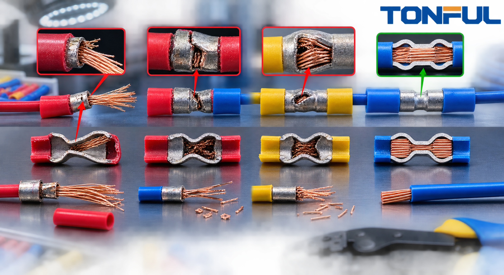

Step-down butt connectors solve an unequal-wire problem, but they create two different crimp interfaces. The large and small ends can use different wire constructions, barrel dimensions, die cavities, crimp-height windows, and pull-force criteria. A symptom at one end can originate from wire preparation, tooling, routing, or sealing elsewhere in the process.
Do not diagnose a failed splice from appearance alone. Preserve the evidence, separate immediate containment from permanent corrective action, and use the product drawing, customer specification, approved process, and test plan as acceptance authorities.
Diagnostic Sequence for a Failed Step-Down Splice
Use the same sequence before changing tools or materials:
- Quarantine the affected lot and related work in process. Stop shipment and identify the earliest and latest potentially affected production.
- Review traceability. Collect connector and wire lots, tool and die IDs, cavity, setting, maintenance status, operator, shift, work instruction, and inspection records.
- Perform visual inspection. Preserve failed parts before cutting; compare both ends with retained accepted samples.
- Measure both crimp heights or controlled dimensions. Do not measure only the visibly failed end.
- Pull-test the small and large ends as separate populations. Record result, failure mode, and acceptance-source document.
- Measure low resistance with a controlled Kelvin setup. Document Force/Sense positions, reference wire length, temperature, and baseline treatment.
- Cross-section selected failed and accepted samples. Correlate the section with crimp height, pull, and resistance.
- Investigate environmental and routing evidence. Review heat, fluids, moisture, salt, abrasion, vibration, bend location, strain relief, and seal recovery.
Do not destroy every failed sample in the first test. Maintain chain of custody and reserve specimens for confirmation.
1. Wrong Barrel Range
Observable symptom: The wire pulls out, strands do not compact, strands cannot enter, or the barrel cracks or deforms abnormally.
Evidence to collect: Exact wire part number and construction, conductor area, insulation diameter, connector drawing and lot, insertion photos, crimp height, pull result, and cross-section from both ends.
Immediate containment: Stop use of the connector-wire combination and segregate all affected lots.
Root-cause confirmation: Compare each conductor with the documented large- and small-end ranges. Confirm that no nominal AWG conversion, insulation color, or visual fit replaced the controlled wire specification.
Permanent corrective action: Select a connector whose two barrel ranges are approved for the exact wires, or obtain a validated custom combination.
Prevention/control-plan change: Add wire part numbers, both barrel ranges, and first-piece fit verification to the bill of materials and work instruction. Start with TONFUL’s step-down butt connector guide.
2. Conductor Size Confused with Insulation Diameter
Observable symptom: The jacket appears to fit the sleeve, but pull force or resistance is unstable; sealing may also be loose or over-compressed.
Evidence to collect: Conductor AWG or mm2, strand construction, measured conductor area where appropriate, insulation material, and insulation outside diameter for both sides.
Immediate containment: Hold substitutions and stop selecting connectors by finished-wire diameter or color alone.
Root-cause confirmation: Compare conductor and insulation data separately with the connector drawing. Thin-wall and thick-wall wires of the same nominal gauge can behave differently.
Permanent corrective action: Approve the full wire construction and sleeve fit, not only nominal AWG.
Prevention/control-plan change: Add conductor size and insulation OD as separate receiving and setup fields. TONFUL’s wire AWG and insulation guide explains the distinction.
3. Incorrect Strip Length
Observable symptom: Copper is exposed outside the barrel, insulation enters the conductor crimp, strands miss the compression zone, or the wire cannot reach the center stop.
Evidence to collect: Actual strip lengths, stripper settings and blade condition, connector section, insertion depth, wire-end photographs, and work-instruction revision.
Immediate containment: Stop the stripping station, preserve samples, and verify the setup against the controlled drawing.
Root-cause confirmation: Determine whether the wrong value, tool wear, wire-position variation, or operator method caused short or long strips.
Permanent corrective action: Correct the strip setting, repair or replace tooling, and requalify samples before restart.
Prevention/control-plan change: Add first-piece and periodic strip-length checks with instrument, frequency, limit, and reaction plan.
4. Cut or Birdcaged Strands
Observable symptom: Reduced pull strength, high resistance, escaped strands, folded strands at the barrel entrance, or early conductor breakage.
Evidence to collect: Magnified stripped-wire samples, strand count before and after stripping, blade and guide condition, insertion video or photos, pull failure mode, and cross-section.
Immediate containment: Stop the stripping process and quarantine wire prepared since the last accepted check.
Root-cause confirmation: Reproduce stripping with the actual wire and inspect for nicks, cuts, twisting, or spreading before insertion.
Permanent corrective action: Use the correct blade, guide, stop, and handling method; replace worn parts and retrain only after the process is corrected.
Prevention/control-plan change: Define allowable strand damage, magnification, sampling, and reaction limits. Review TONFUL’s guide to preventing wire birdcaging.

5. Incomplete Conductor Insertion
Observable symptom: Low pull force, intermittent resistance, unequal insulation gaps, conductor not visible at an inspection point, or a section showing partial engagement.
Evidence to collect: Strip length, insertion depth, inspection-window view, center-stop condition, escaped strands, sleeve geometry, and operator method.
Immediate containment: Hold the lot and inspect both ends of suspect splices with the approved method.
Root-cause confirmation: Reproduce insertion to determine whether insulation, a displaced strand, an incorrect strip length, or connector damage stopped the wire early.
Permanent corrective action: Correct preparation and insertion aids; replace damaged components and make new validated samples.
Prevention/control-plan change: Add insertion marks, windows or depth checks where available, plus first-piece verification for both ends.
6. Wrong Die, Cavity, Setting, or Orientation
Observable symptom: One end is loose while the other is crushed; crimps are off-center; barrel fold, flash, asymmetry, or tool marks differ from approved samples.
Evidence to collect: Tool and die IDs, cavity and setting, connector orientation, crimp-height results, tool calibration and maintenance history, and section profiles.
Immediate containment: Lock the tool, stop production, and identify all material produced since the last verified setup.
Root-cause confirmation: Compare the actual setup with the approved two-end application specification and reproduce the result under controlled conditions.
Permanent corrective action: Install and validate the correct tooling or setting for each end.
Prevention/control-plan change: Use keyed or error-proofed tooling where practical and require setup verification by connector, wire, end, cavity, and orientation. TONFUL’s crimp die selection guide provides general principles.
7. Overcrimping or Undercrimping
Observable symptom: Pullout, high resistance, cut strands, barrel thinning, cracks, excessive flash, or crimp height outside the approved window.
Evidence to collect: Both-end crimp heights, tool setting, force-monitor data where available, pull results and modes, resistance, and accepted/failed cross-sections.
Immediate containment: Stop the process when a controlled dimension is out of limit; quarantine material back to the last accepted verification.
Root-cause confirmation: Correlate the measured height and section with tool setup, wear, material, alignment, and wire construction. Do not equate more compression with a better crimp.
Permanent corrective action: Restore the approved process window, service tooling, and validate both ends before release.
Prevention/control-plan change: Define measurement method, sampling, calibration, trend review, and reaction rules. The Molex Quality Crimp Handbook explains how crimp height, visual inspection, and pull testing work together.
8. Unsupported Bending or Harness Load
Observable symptom: Conductor strands break near the barrel exit, resistance becomes intermittent during movement, insulation shows a sharp bend, or the splice moves under harness tension.
Evidence to collect: Installed-location photos, bend and breakout geometry, clip spacing, service loop, abrasion marks, vibration history, fracture location, and comparison with harness drawings.
Immediate containment: Stop movement or loading, support the harness, and inspect adjacent splices and wires in the same routing zone.
Root-cause confirmation: Reproduce harness motion or vibration and determine whether load concentrates at the rigid splice transition rather than being carried by approved support.
Permanent corrective action: Relocate the splice outside repeated-flex zones, correct routing, and add approved strain relief or mechanical protection.
Prevention/control-plan change: Add splice-location, bend, support, and harness-dress requirements to the drawing and installation inspection. The active NASA-STD-8739.4A workmanship standard addresses interconnecting harness workmanship and design controls; use the applicable project requirements rather than treating it as automatic automotive approval.
9. Seal or Environmental-Protection Failure
Observable symptom: Green or black corrosion, moisture tracks, salt residue, adhesive gaps, split or scorched tubing, loose sleeve recovery, or resistance increasing after exposure.
Evidence to collect: Location and exposure history, seal photographs, recovered dimensions, adhesive flow, wire-jacket condition, heating equipment and cycle, contamination, fluid or salt evidence, and pre/post-exposure resistance.
Immediate containment: Protect the circuit from further exposure, quarantine the affected sealing lot and process window, and inspect similar locations.
Root-cause confirmation: Determine whether the wrong material, incompatible jacket, contamination, incomplete recovery, overheating, abrasion, or unsupported movement breached the protection.
Permanent corrective action: Select and validate the correct sealing and mechanical-protection system, correct the heating process, and replace affected splices.
Prevention/control-plan change: Control material, heater, cycle, recovery, adhesive-flow criteria, cooling, inspection, and environmental qualification. TE’s official automotive heat-shrink protection guidance discusses insulation, strain relief, abrasion, moisture, fluids, corrosion, and splice sealing in harsh vehicle environments. Do not transfer TE product claims to TONFUL products without model-specific validation.

Failure-to-Evidence Matrix for All Nine Causes
| Cause | Observable evidence | Confirmation method | Permanent control |
|---|---|---|---|
| Wrong barrel range | Pullout, rejected strands, abnormal barrel deformation | Compare exact wires with both documented barrel ranges; section and pull-test | Lock approved connector-wire combinations in BOM and drawing |
| Conductor / insulation confusion | Sleeve appears to fit but crimp is unstable | Verify conductor area and insulation OD separately | Control full wire part number and construction |
| Incorrect strip length | Exposed copper, insulation in crimp, shallow engagement | Measure strips and section insertion zone | Controlled stripper setup and periodic checks |
| Cut or birdcaged strands | Missing, folded, escaped, or broken strands | Magnified prep inspection and cross-section | Blade/guide maintenance and strand-damage criteria |
| Incomplete insertion | Unequal gaps, low pull, partial barrel engagement | Depth/window inspection and section | Insertion marks, stops, and first-piece verification |
| Wrong die/cavity/setting | Loose or crushed end, asymmetric crimp | Tool traceability, height measurement, approved-profile comparison | Two-end setup sheet and error-proofing |
| Over/undercrimp | Pullout, cracking, cut strands, high resistance | Crimp height, pull, Kelvin resistance, and section correlation | Process window, calibration, trend and reaction plan |
| Unsupported bending | Strand fracture near exit, intermittent movement fault | Routing review, movement reproduction, fracture analysis | Relocate, support, strain-relieve, and inspect harness dress |
| Seal failure | Corrosion, moisture path, split tubing, resistance drift | Seal section, exposure review, material/heating verification | Qualified sealing system and controlled application process |
Use TONFUL’s crimp pull-force testing guide to structure mechanical evidence. Use a defined Kelvin resistance method rather than continuity alone.
Corrective-Action Release Checklist
Do not restart production only because a replacement sample “looks good.” Confirm containment boundaries, verified root cause, corrected documents and tooling, successful both-end validation, operator and inspector authorization, disposition of affected material, and effectiveness monitoring on subsequent lots.
Share the two wire specifications, failed and accepted samples, connector lots, tooling records, measurements, cross-sections, routing, and exposure history with TONFUL for connector and process review. Final acceptance remains with the product and customer authority.