
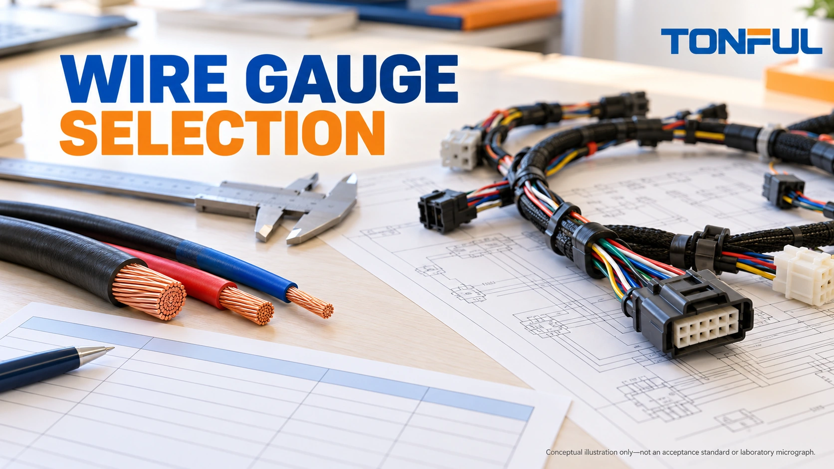
Wire gauge selection for custom harnesses starts with the circuit, not a familiar AWG number. A conductor that runs cool on an open bench may behave differently inside a packed loom beside a heat source. A wire that passes a thermal check can still deliver too little voltage to a distant load, or fall outside the terminal’s approved construction range.
Select a candidate from controlled wire data, then check current duty, complete-path voltage drop, installed thermal conditions and termination compatibility together. This guide provides a calculation example and a copyable selection record. It does not assign universal current ratings to AWG sizes or replace the equipment manufacturer’s design requirements.
On this page: Circuit inputs, Voltage drop, Thermal and mechanical checks, Validation record, TONFUL enquiry.
Define the Circuit Before Selecting a Gauge
Separate operating current from exceptional conditions
Identify what the conductor actually supplies: a motor, heater, solenoid, lighting circuit, electronics feed or signal interface. Record continuous current, intermittent duty, startup waveform and any specified stalled or abnormal condition. A brief peak and a sustained load are not equivalent thermal cases; duration, repetition and protective-device behavior matter.
For several loads sharing a supply or return, document which can operate simultaneously. Do not size a common segment using only the current of one downstream branch. Equally, do not add every nameplate maximum without checking the approved operating sequence. Preserve the load schedule and assumptions so a later feature change triggers review.
Identify circuit protection and the responsible design authority. Review the protection device’s operating characteristics against the conductor, connectors and credible fault conditions under the applicable equipment requirements. Its printed current rating alone does not establish protection of every smaller branch or high-resistance connection. Do not increase the protective-device rating to conceal nuisance operation without engineering approval.
Specify conductor construction, not only AWG
AWG identifies nominal conductor size; it does not identify insulation thickness, strand count, plating, finished diameter or an installed current rating. When a drawing uses square millimeters, verify the actual manufacturer’s construction rather than treating a rounded conversion as an approved substitution.
Request the wire part number, conductor material, strand construction, maximum conductor resistance and reference temperature. Distinguish copper from aluminum or copper-clad alternatives, and verify plating where required. Two wires with similar outside diameters can have different conductive areas because insulation thickness differs.
Choose an applicable wire specification with the customer’s engineering team. Building-wire tables, automotive wire data and aerospace guidance describe different conditions; they are not interchangeable defaults. The wire harness manufacturing process guide explains why the approved wire construction must reach purchasing, cutting, stripping and final production records.
Calculate the Complete-Path Voltage Drop
Define the measurement boundary
For a simple DC circuit, voltage drop is current multiplied by path resistance: Vdrop = I × Rpath. Define Rpath to include the actual supply and return conductors and the connections inside the chosen boundary. Include relevant splices, connector interfaces, switching contacts and shared return segments, or account for them separately with an explicit budget.
If identical supply and return wires each have length L and specified resistance per unit length r, their combined conductor resistance is 2 × L × r. Do not double the length again after entering a total loop length. If the return uses a different wire, chassis path or shared ground, calculate its actual boundary rather than assuming it mirrors the supply.
Use the manufacturer’s maximum resistance data and the applicable temperature adjustment for design calculations. State units consistently: resistance per kilometer cannot be multiplied directly by length in meters without conversion. Use the load’s minimum permissible operating voltage and relevant supply conditions to establish the drop budget; a generic percentage is not automatically suitable for every circuit.

Illustrative calculation, not an acceptance limit
Assume a fictional DC load draws 4 A. Its supply and return wires are each 3 m long, and the assumed conductor resistance is 0.020 ohm/m at the stated calculation temperature. These inputs demonstrate arithmetic only; they are not a wire recommendation or measured TONFUL result.
| Calculation item | Illustrative calculation | Result |
|---|---|---|
| Total conductor length | 3 m supply + 3 m return | 6 m |
| Conductor resistance | 6 m × 0.020 ohm/m | 0.120 ohm |
| Conductor voltage drop | 4 A × 0.120 ohm | 0.480 V |
| Additional connection allowance | Assumed for this example only | 0.040 ohm |
| Total path voltage drop | 4 A × 0.160 ohm | 0.640 V |
| Total path resistive loss | 4 A × 4 A × 0.160 ohm | 2.560 W |
The example shows why a conductor-only calculation can understate the full drop. The 2.560 W is distributed across the defined path; it is not a predicted temperature rise or evidence that every connection dissipates equal power. A small, high-resistance interface can concentrate heat locally.
If the approved voltage budget is exceeded, investigate conductor area, routing length, return design and connection performance. Upsizing the wire cannot correct an unacceptable contact interface by itself. Recalculate at relevant operating conditions, then verify the completed assembly. The harness continuity testing guide helps distinguish a basic connected circuit from an adequately controlled resistance measurement.
Check Bundling, Insulation and Termination Compatibility
Evaluate the installed thermal case
Resistive heating follows P = I²R for the defined resistive path. Heat removal depends on the installed surroundings, so a current limit requires both electrical and thermal context. Record bundle composition, simultaneously loaded circuits, covering, enclosure, airflow, nearby surfaces and installation location. Identify likely hot spots rather than measuring only an accessible outer wire.
NASA’s wire-bundle thermal modeling research examines mixed wire gauges and currents, jacket properties and external thermal conditions. It supports treating bundle ampacity as configuration-dependent. The 2017 research is not a universal industrial sizing standard, a current-rating table for this project or evidence of NASA approval of a commercial harness.
Use the applicable customer-approved method or wire-system guidance for thermal assessment and derating. Do not transfer a fixed bundle reduction percentage between unlike constructions. Separate ambient temperature from conductor temperature and compare the predicted or measured condition with all applicable component limits, including terminals, housings, seals and coverings.
Select insulation for the complete exposure
Temperature and voltage ratings address different requirements. A higher insulation temperature rating does not eliminate conductor heating, and thicker insulation does not establish higher current capacity. Record the actual insulation system and supporting specification, not merely a generic material name.
Check abrasion, fluids, moisture, flame requirements, UV exposure and cleaning agents where relevant. Assess flexing, bend radius and strain relief against the intended movement. Static flexibility does not prove continuous-flex endurance. A substitution that changes insulation outside diameter can also change seal compression and stripping settings even when conductor size remains unchanged.
Verify the wire-terminal-seal combination
Confirm conductor size, strand construction and insulation diameter against the exact terminal and seal documentation. Review the approved tool, applicator or cavity, strip length and crimp acceptance requirements. Larger wire is not automatically a safer replacement if it overfills the conductor barrel or prevents seal seating.
Check terminal current capability within the specified connector population and temperature conditions, not in isolation. Shared cavities, adjacent loaded contacts and installation geometry can change the relevant thermal case. The crimp quality validation guide connects the approved combination to mechanical, dimensional and electrical evidence.

Validate the Installed Design and Record the Decision
Plan a representative validation
Define sample identity, quantity, variants, installation configuration and acceptance sources before testing. Allocate samples for baseline measurements, environmental exposure and any destructive analysis. Explain whether tests share specimens, and retain an unaged comparison sample when the approved plan requires it. Do not treat an undocumented replacement specimen as a continuation of the failed original test.
Use the production-intent wire, terminations, covering and routing. Verify voltage delivered at the load and temperature at the specified critical locations under the agreed load schedule. Document supply condition, current waveform, operating duration and thermal stabilization rule. Test cold-start or transient behavior separately when required; a steady-state result cannot establish every operating condition.
Qualified personnel should use the equipment-specific safe test procedure, protected supplies and appropriately rated instruments. Never apply power to unidentified connections or use resistance mode on an energized circuit. Record instrument range, accuracy, calibration and probe locations; do not let a changed measurement boundary make two results appear comparable when they are not.
Copyable wire-selection record
| Record field | Required entry |
|---|---|
| Circuit identity | Harness part/revision, circuit ID, load and responsible engineer |
| Current profile | Continuous, intermittent, startup and approved abnormal conditions |
| Simultaneous loading | Shared supply/return loads and operating schedule |
| Wire construction | Manufacturer part, material, size, stranding, plating and insulation |
| Resistance input | Maximum resistance, units, reference temperature and correction source |
| Voltage-drop boundary | Supply/return lengths, interfaces, budget and minimum load voltage |
| Thermal installation | Bundle, covering, airflow, ambient and critical component limits |
| Termination system | Terminal/seal parts, approved wire range, tooling and inspection source |
| Protection | Device identity, characteristics and engineering review record |
| Validation | Samples, conditions, probe locations, measured values and acceptance limits |
| Decision | Pass, conditional or rejected; reviewer, date and unresolved actions |
| Change control | Approved substitutions and triggers for renewed assessment |
Keep raw results, calculations and photographs linked to this record. If a terminal temperature fails while the conductor remains acceptable, isolate the interface and installation cause instead of blindly increasing wire size. If load voltage fails without excessive temperature, investigate length and connection losses before changing insulation.
The IPC/WHMA-A-620 buyer guide supports agreement on workmanship acceptance. Workmanship conformity alone does not prove the conductor sizing or system thermal design is adequate.

Work With TONFUL on a Controlled Wire Specification
Send the circuit diagram, load profile, supply and return lengths, installation environment, terminal parts and applicable acceptance documents through TONFUL’s project enquiry channel. Request review of the proposed construction and identify which calculations, material documents and sample tests remain necessary before release.
Approve the specific wire and termination combination, not only an AWG label. Define substitution and routing-change rules so procurement savings, new coverings or additional loads do not silently invalidate the original selection. The final decision belongs to the authorized project team and its documented application requirements.