
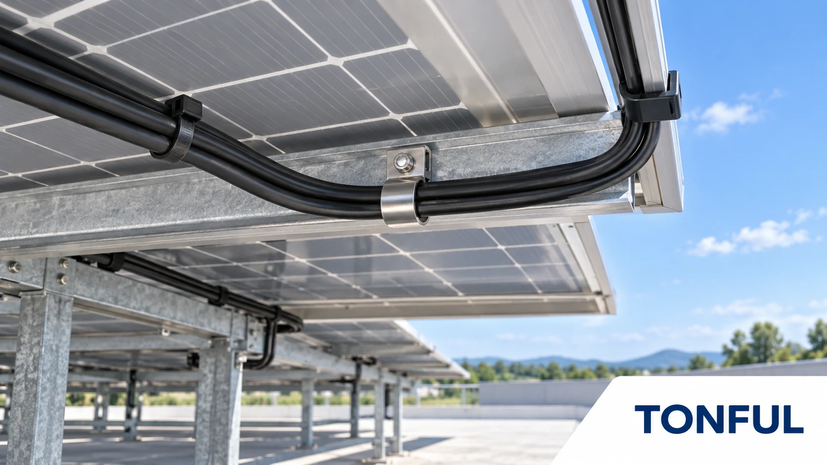
A black cable tie is not automatically a solar-rated cable support. Under a photovoltaic array, cable management must survive sunlight that reaches exposed locations, elevated module temperatures, wet and dry cycles, wind-driven movement, abrasion and years of inspection or maintenance. If a fixing fails, a cable may sag onto a sharp rail or roof surface. A stronger tie alone cannot rescue poor routing or an unsuitable mounting interface.
For long-term primary support of PV string wiring, follow the module, racking, cable and project requirements. Some public-sector PV guidance recommends purpose-designed metal clips or ties instead of plastic ties. A UV-resistant polymer tie should be used only where its exact product evidence and the approved system design permit it. This guide therefore separates bundling, positioning, primary support and solar-array string-wire support rather than treating them as one application. It does not promise a universal outdoor life or describe any TONFUL polymer tie as solar-rated without model-level evidence.
Start With the PV Cable-Management Function
Map the route of every DC string cable, connector lead and transition. Identify the required function before choosing the device. A tie around two loose wires is not necessarily an approved way to suspend them from a module frame.
| Cable-management function | What it means | Evidence and design boundary |
|---|---|---|
| Bundling only | Organizes conductors together at a controlled location | Does not prove attachment, securement or support capability |
| Positioning or securement | Holds cable in a defined route and away from edges or moving parts | Verify fixing interface, retention, spacing and cable movement |
| Primary support | Bears all or part of the cable weight | Requires the applicable support classification, fixing device and end-use approval |
| Solar string-wire support | Supports PV DC cable beneath or around modules and racking | Prioritize module/racking instructions and project requirements; evaluate purpose-designed metal clips or ties |
The U.S. Department of Energy’s PV cable-management best practices describes premature failure of ordinary plastic ties under heat, UV and chemical exposure and identifies metallic clips, hangers and high-weathering alternatives such as PVDF. DOE’s severe-weather PV design guidance is stricter: for the covered resilient-design context, it recommends not using plastic wire ties to secure string wiring and instead using purpose-built metal clips or ties. Its PV installation and commissioning guidance also advises avoiding plastic wire ties that are prone to premature failure. These sources do not certify a specific TONFUL product or establish one universal rule for every jurisdiction, but they prevent a generic UV claim from being treated as automatic PV primary-support approval.
Use the system design, module and racking instructions, cable listing, local code and authority having jurisdiction to define support spacing, bend radius, connector position and accessible inspection points. Qualified personnel should address energized PV circuit work using applicable safety procedures. Do not pull or re-route a live cable simply to test a tie.
Understand Exposure Under and Around Modules
An underside location is not necessarily UV-free. Light can reach frame edges and gaps, while reflected radiation and varying array geometry change exposure. Heat can build beneath modules; a dark tie may run hotter than ambient air. Rain, condensation, salt, dust, agricultural chemicals and cleaning agents may act together with tension.
Record where each tie sits: directly exposed, partially shaded, protected in a raceway, on a module frame, along a rail or at a roof transition. Document orientation and contact with metal, cable insulation and potential sharp edges. Temperature cycling and wind-induced cable motion can create fretting even when the material itself has an outdoor claim.
| Site variable | Evidence to collect | Design question |
|---|---|---|
| Sunlight | Exposure location, orientation, product UV marking | Does the exact model cover this exposure? |
| Heat | Module/roof thermal profile and material evidence | Does performance remain after aging under load? |
| Moisture/salt | Drainage, coastal deposits, cleaning | Does polymer or metal construction fit? |
| Movement | Cable slack, wind, rail edges, thermal expansion | Is abrasion or connector strain controlled? |
| Mounting | Frame/rail geometry, finish and access | Is the fixing device approved for that surface? |
| Maintenance | Inspection frequency and replacement access | Can failure be detected and corrected safely? |
Verify UV and Outdoor Claims
Color is only a clue to formulation, not a certificate. Black pigment may be part of UV stabilization, but two black ties can use different resins, additives and test methods. Ask for the exact part number, material designation, package marking, relevant test report, conditioning, aging method and post-exposure mechanical or locking criteria.
UL Solutions’ cable tie application guidance notes that products may be suitable for UV exposure or outdoor use when marked on the package and investigated for relevant properties. It also distinguishes bundling from products evaluated for primary support. Check the exact certification or report scope; do not assume a generic UL logo or raw-resin recognition extends to the delivered tie or mounting base.
For an IEC-based specification, use the current IEC 62275:2022 fourth edition, which replaced the 2018 third edition. It covers metallic, non-metallic and composite cable ties and associated fixing devices used to manage or secure wiring systems in electrical installations; additional requirements may apply when they support wiring. Laboratory exposure is a screening and qualification tool, not a prediction of every site’s calendar life.
UL’s published classification explanation adds useful boundaries. Types 1 and 11 use a post-exposure breaking-strength evaluation; Types 2 and 21 use a one-minute withstand evaluation; Types 2S and 21S use a five-minute withstand evaluation and are the designations investigated for primary support within the stated scope. The S suffix does not approve every solar installation. UL also states that “Resistant to ultraviolet light” must be tied to the exact product and package marking, and that the long-term effects of UV exposure still require consideration for the final application and geography.
Compare Material and Device Options
Compare Polymer and Metal Options
| Option | Main advantage | Main limitation |
|---|---|---|
| UV-stabilized PA66 | Broad availability and potentially economical bundling or positioning | Moisture, thermal aging and outdoor life require finished-product evidence |
| PA12 | Lower moisture uptake and useful flexibility in some designs | Material name does not establish UV classification or PV approval |
| PVDF | Strong weathering and chemical-resistance potential | Higher cost; exact finished-device evidence and installation approval still required |
| Stainless clip or tie | Avoids polymer UV embrittlement | Edge condition, clamp pressure, corrosion, galvanic interaction and frame compatibility require review |
UV-stabilized PA66 may be suitable for a permitted bundling or positioning function when the exact product’s outdoor evidence and installed load fit the project. Moisture conditioning and temperature should be recorded. PA12 is often considered for lower moisture uptake and flexibility, while PVDF appears in DOE’s discussion of more durable alternatives. None of these material names automatically proves UV life, product strength, primary-support classification or compatibility with a module frame.
The existing nylon 6/6 versus nylon 12 solar guide focuses on polymer comparison. The moisture and storage guide explains why delivered nylon condition can affect test comparisons. Ask for finished-tie evidence for the exact grade, color and size rather than transferring resin data into the assembly.
Stainless Steel and Metal Clips
Stainless ties or purpose-designed metal clips can avoid polymer UV degradation, but alloy, edge condition, lock, coating, galvanic contact and cable pressure must be reviewed. A metal clip designed for the module frame may provide a more controlled support interface than a bare strap. It still requires compatible frame thickness, retention, cable diameter and installation method.
For salt exposure, 304 and 316 are not interchangeable by name alone. The 304 versus 316 cable tie guide addresses alloy selection. Do not claim either grade is universally corrosion-proof, and avoid cut metal tails or sharp edges that can damage insulation.
Edge Clips and Mounting Ties
An edge clip may hold a bundle at a specified offset from a panel without drilling. Verify edge thickness, coating, insertion direction, retention and cable movement on the actual frame. A push mount or screw mount requires its own approved hole, substrate and hardware; it is not interchangeable with an edge clip merely because the strap fits the same bundle.
The edge clip cable tie guide describes the interface. Adhesive bases need separate surface preparation and aging evidence; a tie’s loop strength says nothing about adhesive retention on a hot or dirty rail.

Conceptual illustration only—not an acceptance standard or laboratory photograph. Verify module, rail, cable and fixing-device requirements for the actual installation.
Avoid Installation-Induced Failure
Set the tie or clip where it cannot pinch a cable against a sharp frame, bear directly on a connector boot or create a tight bend. Maintain the cable manufacturer’s bend radius and a controlled service loop. Do not let a tie carry the entire cable weight where an approved support system is required. Verify the actual frame or rail finish and any restrictions in module instructions before attaching a device.
Use a compatible tensioning and flush-cut tool. Excess tension can damage insulation or concentrate stress in the tie; insufficient tension permits sliding and abrasion. Check both minimum and maximum bundle configurations. A stainless strap may need a protective interface and dedicated cutoff tool. Inspect the cut tail, lock orientation and accessibility from the maintenance route.
Keep connectors out of standing water, debris and unsupported tension according to their instructions. Cable-management hardware should not force mated connectors into a new orientation or obscure the ability to inspect them. A well-qualified tie does not make a poor connector installation acceptable.
Qualify the Complete Assembly
Use production-intent ties, clips and cables on the intended module frame or rail. Define sample quantity and allocation, unaged references, sequential or independent exposure groups, mounting surface condition and tool settings. Test the properties needed by the design: loop and locking performance, frame retention, cable pressure, thermal/UV aging, moisture or corrosion and vibration as applicable.
Record the exact exposure method, duration, temperature, orientation, specimen condition and post-aging checks. Separate product certification from project-specific installed-assembly validation. A UV test of a loose tie does not prove a clip’s retention on a coated frame or cable integrity after cyclic movement.
| Record field | Required entry |
|---|---|
| Site and application | Array type, location, exposure zone and drawing |
| Product identity | Tie/clip part, revision, lot, material and marking |
| Mounting | Module/frame/rail identity, geometry, finish and orientation |
| Cable | Type, diameter, weight, bend radius and connector location |
| Installation | Tool, tension/setting, cutoff, spacing and operator |
| Evidence | Product listing/report, test method, sample count and acceptance source |
| Results | Initial and aged locking, retention, damage and failure mode |
| Release | Scope, deviations, approver, date and inspection plan |
Inspect and Maintain Outdoor Cable Management
An O&M plan should inspect sagging cables, broken or brittle ties, displaced clips, sharp cut ends, abrasion, corrosion and pooling debris. Photograph affected locations, identify product lots when possible and contain unsafe areas under the site’s electrical safety plan. Replacing a broken tie with the same unidentified product does not solve the root cause.
When several failures occur, map their orientation, shade, temperature and installation history. Compare failed and retained samples, tool settings, material identity and support geometry. Determine whether failure began in polymer aging, lock slip, frame retention, cable movement or a secondary event. Revise the design and inspection plan before broad replacement.
For a retrofit, record which modules or strings were accessed and whether existing clips, ties and cable jackets can be inspected without disturbing energized conductors. Do not mix new and old hardware without a controlled compatibility review. If a replacement changes cable position, confirm that connector leads retain their intended routing, bend radius and strain relief. Define a safe method for removing old ties without nicking insulation and for accounting for cut pieces, especially where fragments could remain on a roof or in vegetation. Photographs before and after work, hardware lot IDs and a sign-off by the authorized maintainer make later failures easier to investigate.
The cold-weather cable tie failure guide illustrates why visible fracture alone does not identify the original cause. Outdoor life claims should state the specific evidence and inspection assumptions rather than a universal number of years.

Inspect the cable, support interface and nearby connector together; replacing only a broken tie may miss the initiating fault.
Conceptual illustration only—not an acceptance standard or laboratory photograph.
Work With TONFUL
TONFUL’s cable tie range presents polymer, edge-clip and stainless options, but the public page does not currently establish a model-specific solar rating, primary-support approval, UL Product iQ file, IEC/UL 62275 classification or UV-aging result for a named polymer tie. Do not infer those claims from black color, carbon-black language or a general outdoor description.
Send the array layout, cable and frame drawings, site climate, required function, expected inspection access, package-marking requirement, sample plan and evidence needs. TONFUL can identify candidate products and provide available model-level documentation or samples for evaluation. Release must remain limited to the exact product, fixing interface, cable, environment and approved system design.