
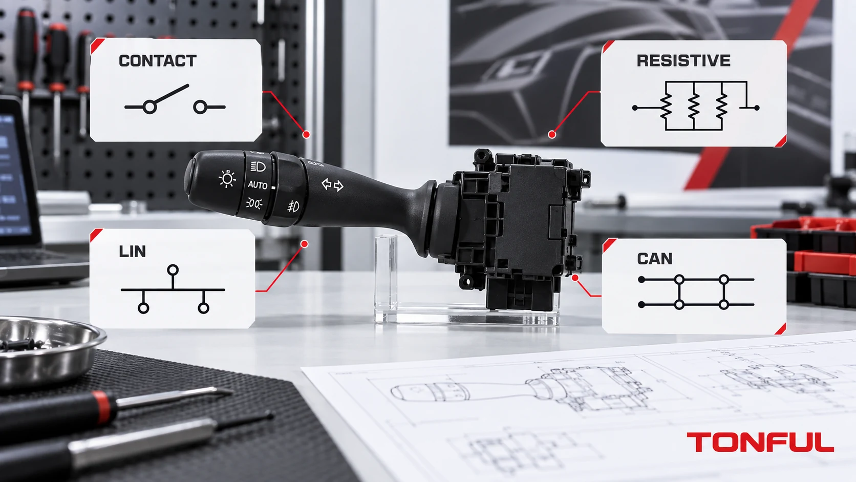
An automotive stalk can look mechanical from the driver’s seat while producing very different electrical outputs behind the steering-column shroud. One version may close independent copper contacts, another may encode several positions through a resistor network, a third may act as a LIN node, and a fourth may send commands through a local controller onto CAN. A matching connector and identical symbols do not prove that these architectures are interchangeable.
For replacement, sourcing and failure diagnosis, the useful question is not simply “Is this switch analog or digital?” It is: what powers it, what signal leaves it, which module interprets that signal, and what product and software evidence controls acceptance? This guide answers those questions without assigning a universal pinout, resistance value, network message or protocol version.
On this page: Architecture Comparison | Identify the Switch | Test Each Architecture | Replacement Release
Architecture Comparison
Direct-Contact or Discrete Analog Switches
A direct-contact stalk closes or opens defined terminal paths as the lever moves through turn, beam, flash, wiper or washer positions. Some contacts may carry a lamp, relay-coil or pump path; others may provide a low-current module input. “Analog” therefore does not automatically mean “high current.” The circuit diagram must identify the actual downstream load.
Diagnosis uses a controlled connector view and a state table. Record the common terminal, normally open or normally closed paths where applicable, every maintained and momentary position, contact overlap or sequence when specified, and loaded voltage drop if the switch carries current. A continuity buzzer alone cannot confirm contact rating, resistance stability, temperature rise or endurance.
Resistance- or Voltage-Coded Switches
A coded switch reduces wiring by presenting different electrical windows for different positions. Several buttons may share a reference, signal and return. The receiving module reads the resulting resistance or voltage and maps it to a command. An open circuit can be a valid rest state in one design and a fault in another.
Compatibility depends on the entire coding network: nominal values, tolerance, contact resistance contribution, reference source, pull-up or pull-down arrangement, test temperature and module decision windows. Measuring a loose switch with a handheld meter may not reproduce its installed voltage because the vehicle’s input circuit forms part of the measurement. Use the approved fixture and method.
LIN Stalk Switches
A LIN stalk contains electronics that read local contacts or sensors and communicate over a single-wire serial sub-network. The node normally also requires supply and ground; additional wake, illumination or discrete lines may be present. Replacing it requires more than matching those wires because node role, addressing, schedule, software behavior and diagnostic support can differ.
The LIN standards overview identifies LIN as an automotive serial-bus family standardized in ISO 17987. The current terminology uses commander and responder; older documents use master and slave. The public standards list establishes the protocol context, not the compatibility of a particular stalk.
CAN-Connected Stalk Functions
Some combination-switch assemblies connect to a steering-column module that places interpreted commands onto CAN; others may contain the network interface within the assembly. The connector can therefore expose local contacts, LIN, CAN, or a mixture. Confirm where translation occurs instead of calling every electronic stalk a “CAN switch.”
CAN compatibility includes physical interface, termination context, bit rate, message definition, node behavior, wake/sleep strategy, software revision, configuration and diagnostics. Bosch’s CAN technology overview provides protocol-family context but does not supply vehicle-specific messages or prove that two nodes are interchangeable.
| Architecture | Typical switch output | Common evidence | Replacement risk |
|---|---|---|---|
| Discrete contact | Separate open/closed paths | Pinout, state table, load path and contact test | Different common path, polarity or current duty |
| Resistance coded | Resistance windows on shared conductors | Network values, tolerance, fixture and module thresholds | Wrong command or implausible-input fault |
| Voltage coded | Voltage windows from reference and return | Supply, pull-up/down, output windows and load | Incorrect reference domain or offset |
| LIN node | Scheduled single-wire serial response | Node description, protocol/software, addressing and diagnostics | No communication or wrong function mapping |
| CAN/local module | CAN frames or locally interpreted signals | Architecture, DBC/service data, software and configuration | Network faults, wrong messages or unavailable functions |

The same driver action can create a contact path, coded level or network request; verify the architecture from controlled vehicle documentation.
Identify the Switch
Start With Vehicle and Part Identity
Record make, model, market, production or chassis/VIN boundary, LHD/RHD, stalk side, trim and relevant options. Capture the complete OE service number, suffix, supplier number, hardware revision and software revision where present. A housing or casting number may identify only a shared subcomponent. The combination-switch OE-number guide explains why number type and supersession direction must be retained.
Photograph the connector straight-on with latch orientation visible. Record every cavity, populated terminal, empty position, shield, twisted pair and conductor size. A twisted pair may prompt investigation of a differential network, but visual appearance is not sufficient identification. Likewise, three wires do not automatically mean LIN; they could be supply, reference and coded return.
Follow a Non-Destructive Identification Sequence
- Retrieve the vehicle-specific wiring diagram and connector view.
- Identify module power, ground, references and communication lines before probing.
- Determine whether the stalk contains electronics from the diagram, product drawing and current behavior.
- Compare removed and candidate part numbers, populated cavities and revisions.
- Select the approved test tool: ohmmeter/continuity fixture, powered coded-signal fixture, LIN analyzer, CAN interface or vehicle diagnostic tool.
- Protect network lines and module inputs; do not apply battery voltage or a test lamp to an unidentified signal.
- Record initial DTCs and live states before disconnecting or clearing anything.
TONFUL’s pinout and connector guide adds practical connector-view and state-table controls. It should not be used as a generic wiring diagram.
Recognize Mixed Architectures
Many assemblies are hybrids. Turn-signal contacts may be read locally while wiper speed uses a resistor ladder, illumination is PWM controlled and commands leave a steering-column module over CAN. Build one architecture record per function group rather than assigning one label to the entire housing.
This also changes sourcing risk. A mechanical switch may be governed mainly by contacts, springs and geometry. An electronic assembly adds PCB revision, components, firmware, programming, ESD handling, end-of-line communication test and change control. Similar fit, form and lever feel do not cover these differences.
Test Each Architecture
Use an Architecture-Specific Test Matrix
| Test field | Discrete | Resistive/voltage coded | LIN | CAN/module based |
|---|---|---|---|---|
| Power required | Usually not for dry continuity; required for loaded test | Controlled reference may be required | Defined supply, ground and wake | Defined module and network supply |
| Primary observation | Contact state/path | Raw value and decoded command | Node communication and signal state | Module input, message/state and DTCs |
| Instrument | Continuity/low-resistance system and load fixture | Calibrated meter or data acquisition with fixture | Approved LIN analyzer/diagnostic tool | Approved CAN/vehicle diagnostic tool |
| Revision control | Pinout and mechanics | Coding network and thresholds | Hardware, software and node data | Hardware, software, configuration and messages |
| Typical false conclusion | Beep equals load capability | Meter value equals installed value | Bus waveform equals correct application data | No DTC equals complete functional equivalence |
For discrete paths, test every maintained, momentary and transitional position specified by the drawing. If load is carried, evaluate under the approved electrical load and switching sequence. The contact-resistance testing guide explains why test points and conditions must be controlled.
For coded inputs, record instrument model, range, accuracy, Force/Sense arrangement when applicable, supply or reference, temperature, raw result, specified window and decoded module state. Do not average away an intermittent contact or hide contact contribution by subtracting an undocumented fixture value.
For LIN, confirm supply, ground, wake behavior, bus level, node response, schedule participation, diagnostics and each requested stalk state. NXP’s UJA1023 LIN I/O responder illustrates how a LIN device can read a switch matrix and expose I/O functions. It is an implementation example, not evidence that a particular combination switch uses that part or topology.
For CAN or module-based assemblies, distinguish the local switch input from the controller’s network output. Confirm recognized lever state first, then the authorized downstream response. Monitor communication errors, DTCs, wake/sleep and current consumption under the project plan. A valid electrical frame is not enough if its identifiers, scaling or software semantics do not match the vehicle.
Diagnose Symptoms Without Guessing
| Symptom | Likely investigation | Evidence |
|---|---|---|
| One discrete function is open | Contact, conductor, terminal or common path | State table, dynamic continuity and terminal inspection |
| Several coded positions report one command | Resistor network, reference, return or threshold mismatch | Raw values and module-decoded states |
| Switch works on bench but not in vehicle | Fixture omitted module load, reference, coding or network dependency | Installed signals and vehicle configuration |
| LIN node is silent | Supply, ground, wake, bus, address or hardware/software mismatch | Physical-layer trace and diagnostic session |
| CAN DTC appears after replacement | Wrong node, revision, coding, termination context or software | Network errors, part data and configuration records |
| Functions are delayed or intermittent | Contact bounce, harness movement, network errors or wake state | Time-correlated input, bus and DTC evidence |
| Primary functions work but illumination does not | Separate supply, polarity, PWM or coding path | Illumination circuit and dimming command |
| No fault code but function is wrong | Valid communication with incorrect mapping or variant | Command matrix compared with vehicle behavior |

Select the measuring method only after power, signal type, node role and receiving module are identified.
Replacement Release
Approve a candidate only when mechanical interface, complete OE chain, connector keying, populated cavities, power and ground, architecture, every function state, software/configuration and installed vehicle behavior agree with controlled requirements. Record sample and lot, vehicle, document revisions, instrument, fixture, environmental condition, raw results, acceptance source, approver and date.
Do not assume that a networked replacement self-configures. Follow the vehicle-specific coding, initialization or calibration procedure and retain pre- and post-installation DTCs. Sample approved applies only to the named configuration; it does not automatically release other model years, markets or suffixes. The combination-switch diagnostic guide helps separate stalk evidence from wiring, modules and downstream loads.
Work With TONFUL
TONFUL’s automotive combination switch range presents current application references. Send the exact vehicle scope, complete OE number, connector views, cavity map, circuit diagram, required functions, architecture, hardware/software information and approval plan. TONFUL can review a candidate against controlled product evidence and an approved sample; connector fit or protocol naming alone is not treated as interchangeability proof.