
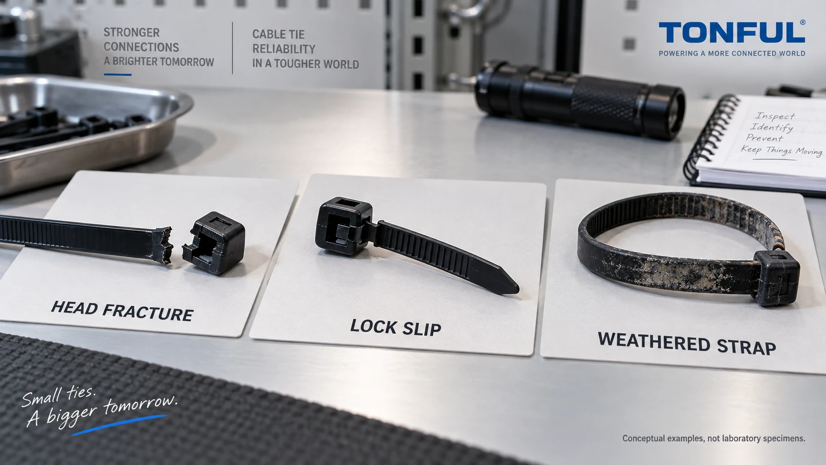
When a cable tie fails, the visible broken strap is often the end of a longer chain of events. A clip may have moved first, exposing the tie to an edge. A bundle may have grown during service. A tool may have over-tensioned the head. Heat, ultraviolet light, chemicals and moisture can act together, while a poor storage or installation condition can make one lot appear weaker than another. Replacing the tie without locating the first failing interface may repeat the problem.
This guide provides a practical failure-analysis path for cable ties used in equipment, vehicles and outdoor wiring. It separates fracture, slip, brittle behavior and mounting failure, then links each symptom to evidence, confirmation tests and lasting controls. It does not diagnose a product from color alone or invent universal force, temperature or life limits.
Contain the Failure and Preserve Evidence
If loose cable could touch energized parts, sharp metal, moving machinery or a hot surface, isolate the hazard using the site’s qualified-person procedure. Photograph the tie and cable route before moving them. Tag the location, orientation, nearby support points and the first sign of abrasion or heat. Keep fragments, the locking head, cut tail and an unfailed tie from the same area when safe to collect. Do not discard the failed part before recording its lot and installation history.
Quarantine affected lots or installations when a common problem is plausible. Determine the scope by part number, revision, material, color, manufacturing lot, warehouse condition, tool, operator, station and service date. A single outdoor failure after years of exposure differs from a cluster of new ties breaking during assembly. Containment is not the same as root-cause confirmation: temporary extra support may be needed, but it should not become an undocumented design change.
The UL cable-tie application guidance emphasizes exact product markings for strength, material, installation and environmental suitability. Use the actual package and certification record, where applicable, rather than assuming an unmarked tie is equivalent to the approved one. Loop strength and fixing-device strength are different properties; neither alone proves installed performance.
Start With a Failure-to-Evidence Matrix
| Observed symptom | Evidence to preserve | Root-cause question | Immediate control |
|---|---|---|---|
| Fracture at locking head | Head, pawl, tool setting, tail cut | Over-tension, molding flaw or wrong bundle size? | Stop affected tool/lot pending check |
| Fracture on strap bend | Crack origin, bend radius, aging, contact surface | Sharp edge, cold installation or degraded material? | Protect route and collect comparisons |
| Tail pulls through head | Tooth wear, insertion direction, bundle shrinkage | Lock engagement or reverse installation? | Replace with verified tie and method |
| Whole tie intact, cable sags | Mount, hole/edge, support spacing | Fixing failed before tie? | Re-support with approved hardware |
| Surface chalking or brittleness | Exposure map, retained sample, material ID | UV/heat/chemical aging or lot issue? | Inspect comparable exposed locations |
| Jacket nick or flattening | Tie edge, cutoff, tension, cable type | Installation damage despite tie retention? | Remove harmful pressure safely |
| Corroded metal tie or clip | Deposits, alloy/coating record, wetness | Crevice or galvanic system failure? | Preserve corrosion evidence |
This matrix directs investigation, not an automatic diagnosis. One symptom can have several causes. For example, a head fracture could begin with excessive installation tension, a molding defect or later overload. Confirm the initiation site and service sequence before selecting a corrective action.

Conceptual failure categories only; real fracture surfaces and acceptance decisions require preserved samples and product-specific evidence.
Breakage at the Head or Strap
First identify where the crack began, not just where the pieces separated. The transition between strap and head is a common stress concentration because tension, bending and the pawl load meet there. A cracked head may show a whitening zone, a notch left by a tool, or a sudden brittle surface. Record the installation tool, tension setting, cutoff blade, bundle diameter and whether the operator pulled at an angle. Compare those details with the approved work instruction.
A strap break away from the head shifts attention to routing. Check whether the tie crossed a sharp bracket, was folded tightly around a small bundle, or rubbed during vibration. A dark mark may be external contamination, while a polished patch suggests repeated contact. Sectioning or microscopy may be useful when visual evidence cannot establish the origin. Do not claim that every clean-looking fracture is a material defect.
Recreate installation with production-intent ties and the actual bundle. Use the specified tool and an independent checked tool, then compare damage. If the part fractures only with one tool or at one station, investigate setting drift, blade condition and operator method. If several lots fail under controlled installation, review material, molding and conditioning records. The TONFUL loop-tensile guide explains why a catalog rating cannot be treated as installed working load.
Locking Slip and Loss of Tension
A tie can remain unbroken yet stop holding the bundle. Preserve the exact tooth engaged in the pawl, tail insertion direction and head orientation. Check for incomplete engagement, damaged serrations, a cracked pawl, a contaminated head or a tail that was cut too short for inspection. A releasable tie may have been opened accidentally or reused beyond its approved procedure; do not equate its release feature with unlimited service life.
Also measure the bundle after failure. Soft conduit, foam sleeves or a group of cables can compress or settle, reducing tension even when the pawl still holds. Thermal expansion and contraction can alter the fit. If the route is subject to vibration, watch for gradual tie migration or a mount that moves while the loop remains tight. Static loop testing alone may miss these interactions.
The TONFUL releasable-tie guide provides construction context. For diagnosis, test the exact head and strap after relevant conditioning, then inspect the cable bundle under the approved load and movement profile. Separate a tie-lock failure from an incorrect initial tension or a changing bundle.
Brittleness, Cold and Moisture Condition
An apparently brittle tie may have been installed cold, stored incorrectly, aged by heat or UV, contacted by a chemical, or molded from an unsuitable material. The degree and direction of damage matter. Compare sheltered and exposed ties from the same installation, new retained stock from the same lot, and a known-good lot. Record storage packaging, time since opening, humidity exposure and temperature at installation. Nylon moisture state can change flexibility and test results.
The TONFUL moisture and storage guide explains why controlled handling matters. The cold-weather failure guide is useful for a focused low-temperature investigation, but do not assign a universal minimum temperature to all grades from a blog example. Use the exact model’s declared installation and operating limits and the applicable conditioning plan.
Cold installation and cold operation are different questions. A tie that was formed around a bundle at room temperature may respond differently from one bent sharply while already cold. Test both only if the product and application require them. Avoid heating a failed tie or soaking it before analysis unless the procedure records that treatment; it may erase the original fracture or moisture evidence.
UV, Heat and Chemical Degradation
Outdoor exposure is often combined, not a single UV variable. Under solar arrays, reflected light, high temperatures, wet/dry cycles, dust, salt and cleaning chemicals may act together. The U.S. Department of Energy’s PV cable-management guidance describes premature failure of ordinary plastic ties and the routing consequences. It does not establish a universal service life or prove that every black tie is UV resistant.
Map failure by sun exposure, shade, orientation and proximity to a heat source. Check whether chalking, color change, cracks or loss of flexibility occurs only in the exposed zone. If degradation is concentrated at a chemical splash or cleaning path, preserve residue and obtain the actual chemical identity and concentration. Do not rely on the resin name alone; stabilizers, colorant, molding and installed stress affect the finished tie.
Where a claimed UV or temperature rating matters, compare the exact part’s package marking and test report with the specified exposure. A short accelerated-aging result is not a direct year-for-year lifetime conversion unless a validated model and field correlation support it. Consider an approved metal clip, higher-grade polymer or route change if the installed environment cannot be served by the original tie.
Mounting and Cable Damage
If the whole tie remains intact but the cable drops, inspect the mount first. A fir-tree stem can back out of an oversized hole, an edge clip can slide along a flange, a screw base can rotate, and an adhesive base can separate from a contaminated surface. Each needs a different corrective action. The TONFUL edge-clip guide helps identify clip-specific interfaces; do not call all four failures “weak ties.”
If the cable jacket is nicked or flattened while the tie holds, check strap width, installed tension, head location, tail cutoff, sharp mounting edges and service movement. A stronger tie can worsen insulation damage if installed with the same excess force. Trace the load path from cable through loop and mount to substrate. Record which interface first moved or failed, and whether the damage occurred during installation or later service.

The first failed interface may be the mounting point or cable contact, not the visible strap.
Confirm Root Cause With a Controlled Plan
Use a staged sequence: identify the lot and route, inspect failed and comparison parts, review tool and storage records, measure the relevant tie and mount dimensions, recreate installation, run product-specific locking or loop tests, then apply environmental or movement testing only where indicated. Preserve unaged controls. If destructive analysis is needed, assign samples before testing and keep a record of cuts, cleaning and microscopy.
| Test-record field | Required entry |
|---|---|
| Sample identity | Part, revision, lot, location and service history |
| Failure | Location, photographs, crack or slip direction |
| Installation | Tool, setting, operator, bundle and mount |
| Environment | Temperature, UV, chemicals, moisture and duration |
| Comparison | Retained lot, adjacent good part and unaged control |
| Test | Method, fixture, sample count, raw result and failure mode |
| Decision | Acceptance-source document, root-cause evidence, reviewer |
Do not substitute a new part and declare the problem solved merely because one sample passes a pull test. Confirm that the proposed change addresses the initiating mechanism: tool setting for over-tension, a different mount for pull-out, material or route for environmental degradation, or a control-plan update for mixed lots. Validate the changed assembly under the relevant customer requirements and keep the approved scope narrow.
Prevent Recurrence in Production and Service
Translate the finding into measurable controls. Material identity and conditioning may need supplier and warehouse checks. Critical mold features may need dimensional inspection. Tension tools require setup verification and maintenance. Operators need a visual acceptance example for fully engaged heads, flush tails and seated mounts. Installation records should identify part and lot where a field campaign may be necessary.
For service teams, define when to replace neighboring ties and when a route inspection is required. Replacing every tie in an array or vehicle may disturb otherwise sound wiring; replacing only the visibly broken tie may miss common exposure. Use the failure map and safety assessment to set a controlled scope. Any new material or fastening method needs approval against the original drawing and installation conditions.
Request TONFUL Support
TONFUL’s cable tie range can be reviewed against the failed installation. Provide failed and unused samples, lot records, photos before removal, bundle and mount drawings, exposure history, tool settings and the acceptance-source document. Request a candidate design and production-intent samples for a controlled comparison, not a generic “stronger tie” substitution.
The final report should state what failed first, how the cause was confirmed, which locations or lots are affected, what changed, who approved it and how effectiveness will be checked. If evidence is inconclusive, say so and keep the affected release on hold rather than writing a confident but unproven material explanation.