
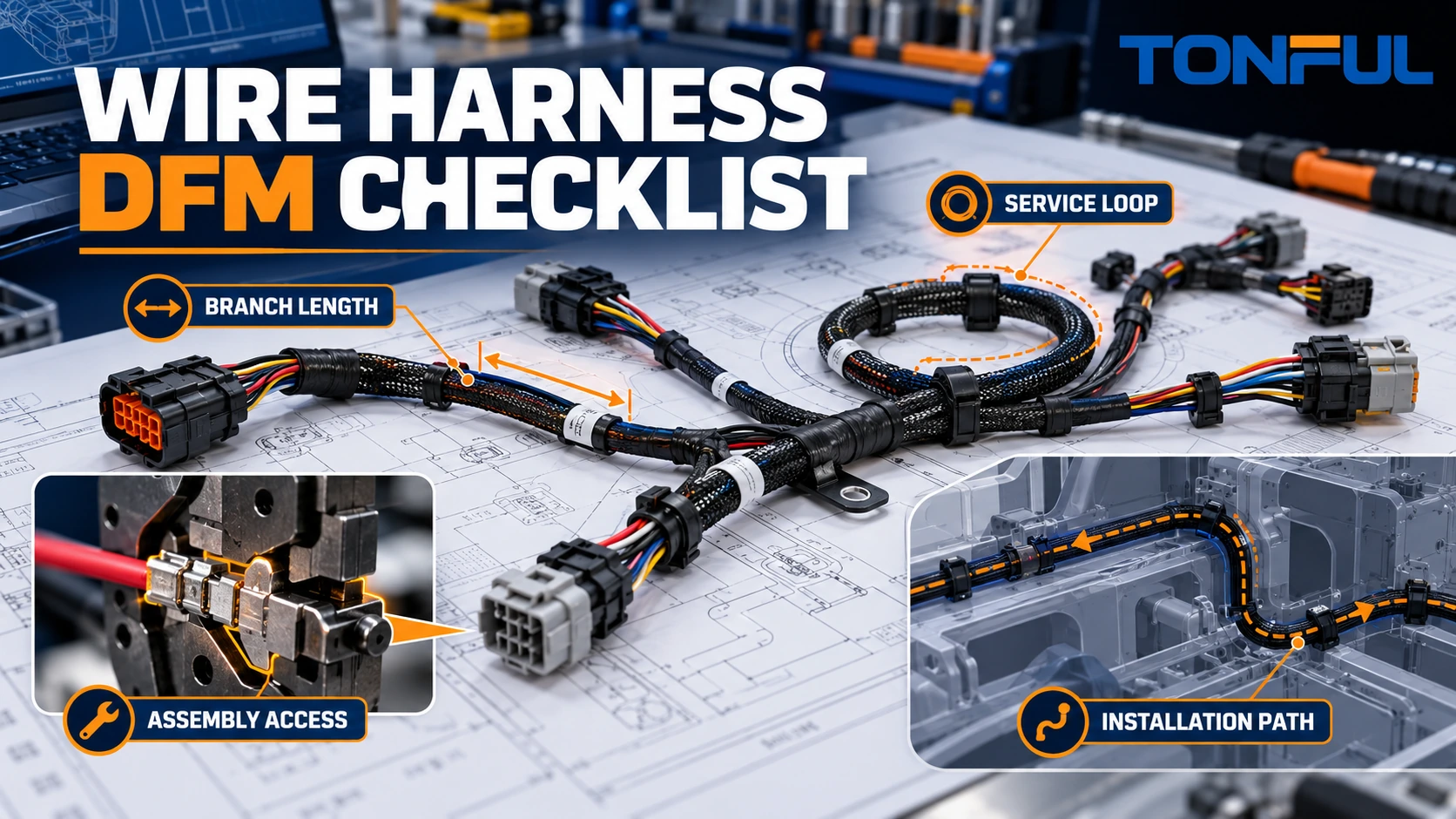
Wire harness design for manufacturing is the process of making the approved electrical design practical to cut, terminate, fixture, protect, inspect and install. A circuit can be electrically correct yet difficult to build consistently because branch dimensions accumulate, connectors cannot reach their mating points, coverings block inspection, or tools cannot approach a terminal, splice or tie location.
A useful wire harness DFM review does not give manufacturing authority to change the design silently. It identifies risks, records assumptions and returns controlled questions to the design owner before release. The checklist below focuses on geometry and access: datums, branch lengths, service allowance, bend transitions, breakout construction, covering boundaries, tool clearance, test interfaces and the equipment installation path.
On this page: Inputs | Geometry | Service loops | Breakouts | Access | Installation | Checklist
Start With Controlled DFM Inputs
Review the harness together with the equipment. The minimum input set normally includes the electrical schematic, circuit list, harness drawing, 3D routing or installation model, connector and terminal data, BOM, applicable workmanship requirements, environmental zones and test plan. Identify the controlling revision for every input and record conflicts rather than choosing the easiest interpretation.
IPC lists IPC-D-620 among its design standards for cable and wiring harnesses. Use only the revision and requirements invoked by the contract or design authority; the standard’s existence does not make every clause or class an automatic project requirement.
Define the production stage. Prototype hand builds can tolerate temporary methods that are unsuitable for repeat production. Serial DFM must consider cutting and stripping equipment, applicators, fixtures, board layout, covering processes, labels, electrical-test interfaces, packaging and line-side presentation. The TONFUL wire harness manufacturing process helps map drawing fields to actual operations.
DFM also needs a release boundary. Mark each item as accepted, accepted with a controlled condition, open, or rejected. Give open actions an owner, due date and affected drawing feature. A supplier suggestion becomes a requirement only after the authorized design record is updated.
Dimension Branches From Functional Datums
Use datums that production and inspection can locate repeatedly: connector mating faces, terminal centers, defined breakout centers, clip centers or cable exits. Avoid dimensioning from soft tape edges, variable boot tips or an undefined “end of loom.” The drawing should state whether dimensions follow the harness centerline, a straightened condition, a fixture path or another method.
Dimension branches from a common functional datum where possible. Long chains of segment dimensions can accumulate tolerance so the final connector misses its installation point. If chain dimensions are necessary, analyze the stack and identify the critical installed relationship. Do not assign tight tolerances everywhere; apply them where fit, sealing, clip engagement, motion or service access requires control.
| Geometry question | DFM evidence | Release risk |
|---|---|---|
| Where is the datum? | Drawing symbol and measurement method | Different inspectors obtain different lengths |
| How is breakout position controlled? | Fixture point, tolerance and covering boundary | Branches reach the wrong side of equipment |
| What is the installed route? | 3D path, mock-up or equipment sample | Drawing length does not fit the real path |
| Which dimensions stack? | Tolerance analysis | End connector shifts outside fit window |
| Are clips clocked? | Orientation view and fixture check | Clip enters panel in the wrong direction |
Allow for connector backshells, seals, boots and required bend transition. A wire length calculated between cavity points may not equal the finished harness dimension after termination, routing and covering. Production allowances should be documented in the controlled manufacturing definition, not improvised by operators.

Conceptual DFM geometry review; the approved drawing and equipment interface define the actual datums and tolerances.
Use Service Allowance for a Defined Purpose
“Add a service loop” is not a complete instruction. Extra length may support connector mating, component removal, door or panel motion, vibration isolation, strain relief, future repair or tolerance absorption. State the purpose, location, routing envelope and retention method. Otherwise, excess wire can become a snag, rub against an edge, violate bend limits or interfere with airflow and moving equipment.
Differentiate a controlled service allowance from an uncontrolled coil. A removable module may need enough free length to disconnect outside the enclosure. A moving joint needs a designed flex path, neutral axis and support. A stationary connector may need only a smooth approach that avoids axial load. Dynamic applications require cable, conductor, bend, speed, torsion and cycle evidence; the continuous-flex harness design guide covers those additional controls.
Define how the allowance is formed and verified. Use a fixture feature, routing clip, loop envelope or length dimension. Confirm that the loop cannot migrate into heat, sharp edges, mechanisms or electrical noise zones. If field service requires repeated movement, include the service action in validation rather than approving the harness only in its installed rest position.
Design Breakouts, Bends and Coverings
A breakout concentrates wires, coverings and mechanical loads. Define the branch sequence, breakout location, transition length and protection method. Avoid abrupt exits that force the smallest branch around the edge of a thick trunk. Provide enough transition for the selected tape, sleeve, tube or molded part without covering a connector seal, clip, label or required inspection area.
Minimum bend behavior depends on the exact wire/cable, bundle construction, covering and service condition. Do not publish one universal bend-radius multiplier for every harness. Use product evidence and application validation, especially near backshells, splices, coaxial cable, twisted pairs or controlled-geometry circuits.
The covering must match the risk. Tape can provide flexible bundling; braided sleeve can support abrasion protection and branch transitions; conduit can provide stronger mechanical separation; heat-shrink can localize insulation or sealing. The TONFUL harness protection guide compares these methods. The drawing should define material, start/stop boundaries, overlap or installation rule where controlled, and how the termination is secured.

Conceptual routing examples—not universal bend or loop dimensions. Validate the exact harness in its equipment envelope.
Verify Assembly, Tooling and Inspection Access
Every termination needs process access. Confirm that wire length and adjacent branches allow stripping, seal loading, crimping, soldering or splice formation with the approved equipment. A very short branch near a large connector may not fit the applicator or hand tool. Closely spaced splices can create a rigid lump, prevent covering installation or make cross-section and repair work difficult.
Review the sequence, not only the finished shape. Ask when seals, sleeves, boots, labels and hardware must be loaded. Confirm that a heat-shrink tube can pass over the largest feature before recovery. Check whether a backshell must be placed before contacts are terminated and whether the finished connector can pass through the selected sleeve or fixture opening.
Inspection access matters too. Keep critical crimp, solder, seal and lock features visible until their required inspection is complete. Do not place tape or overmold over an acceptance feature before it is verified. Define first-piece checks after tool, material or setup changes. The TONFUL crimp pull-force guide explains how process evidence differs from a visual judgment.

Conceptual assembly-access study. Tool envelopes and process order must match the approved production equipment.
Review the Equipment Installation Path
Model the route from package to final connection. Can the largest connector pass through the panel opening, conduit, grommet or channel? Can clips be inserted in the required order? Does a branch need to pass behind equipment before another connector is mated? Check service clearances for hands, locking levers, torque tools and removal.
Protect terminals and locks during installation. Do not use a connector or branch as a pulling handle unless the product and procedure explicitly permit it. Define temporary caps, pull aids or installation fixtures where needed. Confirm that harness coverings do not increase diameter beyond pass-through limits and that labels remain readable after routing.
Installed checks should include mating/lock confirmation, clip seating, edge clearance, bend transition, service movement and absence of tension at connectors. Automotive packaging examples in TONFUL’s heat-and-space harness guide illustrate why electrical correctness alone does not establish routing suitability.
Control Testing, Variants and Changes
Design accessible electrical-test interfaces and define every intended circuit, prohibited short and shield path. If a connector cannot tolerate repeated production mating, approve an adapter or test interface that preserves terminal condition. Record fixture and program revisions with the product result.
Plan variants deliberately. Optional circuits, connector versions or branch lengths should have unique part numbers or a controlled configuration method. Poka-yoke can include keyed fixtures, barcode-controlled programs, component detection and visual aids, but every device needs a challenge test and reaction plan.
Revisit DFM after changes to connector, terminal, wire, cable, covering, clip, splice, tooling, fixture, route or equipment interface. A seemingly minor source substitution can alter stiffness, diameter, strip behavior or tool access. High-mix and prototype programs particularly benefit from the release controls described in TONFUL’s HMLV harness manufacturing guide.
Wire Harness DFM Release Checklist
| Check field | Evidence required | Status / owner |
|---|---|---|
| Controlled input revisions | Document index and conflict rule | |
| Functional datums | Drawing and measurement method | |
| Branch dimensions/tolerances | Fixture or inspection plan | |
| Tolerance stack | Critical installed relationship | |
| Connector/clip orientation | End views and clocking control | |
| Service allowance | Purpose, envelope and retention | |
| Bend transitions | Product evidence and route review | |
| Breakout construction | Location, sequence and protection | |
| Covering boundaries | Material and start/stop controls | |
| Tool access | Equipment envelope and process trial | |
| Inspection access | Feature visibility and timing | |
| Installation path | Mock-up, 3D review or equipment trial | |
| Test interface | Approved fixture and program | |
| Variants/poka-yoke | Configuration and challenge test | |
| Open actions | Owner, due date and release impact | |
| Approval | Design, manufacturing and quality sign-off |
Review Your Harness DFM With TONFUL
Send TONFUL the controlled drawing, circuit list, BOM, connector data, 3D route or equipment constraints, tooling assumptions, protection requirements and test plan. TONFUL can review branch geometry, process sequence, termination access, coverings, fixtures and inspection points against the defined project. Final changes should be released through the authorized drawing and change process before production.