
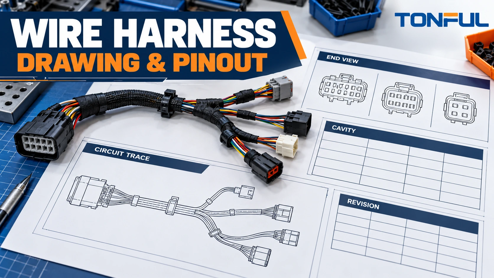
A wire harness drawing connects several kinds of information: electrical intent, physical routing, connector interfaces, materials, workmanship and test requirements. Reading only the line diagram can miss a reversed connector view. Reading only the pin table can miss branch length, splice location or shield treatment. A reliable review follows a controlled order and confirms that every view describes the same assembly revision.
This guide explains that order for engineers, buyers, inspectors and technicians. It does not provide a universal pinout. Connector numbering, symbols and drawing conventions vary by manufacturer and project, so the title block, legend, connector data and approved circuit table always control the interpretation.
On this page: Document control | Drawing types | Connector views | Circuit table | Splices and shields | Dimensions | Verification
Start With the Title Block and Document Control
Read the title block before interpreting a single wire. Record the buyer part number, assembly name, drawing number, revision, date, units, scale note, sheet count and approval status. Confirm that the BOM, pin table, test specification and change notice reference the same released revision. A marked-up PDF or supplier worksheet is not automatically production authority.
Review the revision block and change description. A change may affect only a label, or it may move a cavity, replace a terminal, alter a branch length or change a test program. Identify the effective lot, serial range or purchase order. If old and new configurations can coexist, the drawing package needs a clear transition and traceability rule.
| Control question | Evidence to check | Risk if missed |
|---|---|---|
| Is the drawing released? | Approval status and signatures | Building from an uncontrolled draft |
| Do supporting files match? | Revision index | BOM, pinout and test program disagree |
| What changed? | Revision description/change notice | Wrong rework or incomplete validation |
| When is it effective? | Lot/order/serial boundary | Mixed configurations in one shipment |
| Which document wins a conflict? | Contract precedence rule | Supplier chooses a convenient answer |
IPC lists IPC-D-620 as a design and critical-process standard for cable and wiring harnesses. IPC/WHMA-A-620 addresses assembly requirements and acceptance. Neither replaces the project drawing: the contract must identify the applicable document, revision, class and customer additions. TONFUL’s IPC/WHMA-A-620 guide explains this boundary.
Separate Schematic, Layout and Assembly Information
An electrical schematic shows functional connections, but usually not the physical harness route. A harness layout shows branches, connectors, clips, coverings and dimensions, but may simplify circuit logic. A formboard or fixture drawing supports assembly positioning. A connector detail establishes orientation and cavities. A circuit schedule links these sources.
Do not assume that a line crossing is a splice. Use the legend: a junction dot, splice ID or table reference may indicate connection, while crossing lines without a connection symbol may remain electrically separate. Likewise, a dashed outline can represent shielding, a subassembly, optional content or a reference boundary depending on the drawing convention.
The TONFUL wire harness manufacturing process guide shows how these records enter cutting, termination, subassembly, board build and final test. Reading the drawing in process order helps reveal missing information before production.
Confirm the Connector View Before Reading Cavities
The most common pinout error is reading the correct numbers from the wrong side. A connector drawing may show the mating face, wire-entry face, terminal side or a section. Male/female terminology can refer to contacts or housings and is not a safe substitute for an explicit viewing direction.
Find the orientation note and physical landmarks: latch, key, polarization rib, cavity shape and numbering marks. Confirm whether the drawing says “view into mating face” or “view into wire side.” Compare the controlled connector manufacturer’s drawing with the harness detail. When the housing can accept multiple keys or inserts, verify the full part number rather than using a generic shell image.

Conceptual connector views—not a universal numbering pattern. Use the exact connector manufacturer’s drawing and declared viewing direction.
Treat cavity number, terminal position and circuit name as separate fields. Some connectors include blank, sealed or mechanically blocked positions. An unpopulated cavity is not automatically available for another circuit. Record plugs, seals, secondary locks and terminal types as part of the connector definition.
For safe electrical work, never apply power or ground to an unidentified cavity. Never use resistance or continuity mode on a powered circuit. Module, network, sensor and safety-related interfaces require the approved equipment procedure and protected breakout methods. A general harness pinout does not authorize probing vehicle SRS or other safety circuits.
Trace Each Circuit Through the Pinout Table
Read one circuit end-to-end instead of scanning colors. A useful circuit table includes source connector/cavity, destination connector/cavity, circuit name, wire ID, color, gauge or cross-section, conductor/cable element and special processing. Wire color aids identification but should not be the primary key because colors can repeat, include stripes or vary by approved source.
| Field | What it should tell you | Verification question |
|---|---|---|
| Connector ID | Which physical interface | Does it match the layout label? |
| Cavity | Exact housing position | Is the viewing direction declared? |
| Circuit/net name | Electrical function | Is the same name used on the schematic? |
| Wire ID | Unique production/inspection reference | Is marking method defined? |
| Color | Visual identifier | Are base/stripe conventions clear? |
| Size | Conductor gauge or cross-section | Does it match terminal range? |
| Destination | Other end, splice or device | Can the complete path be traced? |
| Special control | Pair, shield, polarity or processing | Is it represented in test data? |
Trace power, return, signal and protective paths independently. For branched circuits, follow the wire to the splice table and then to every destination. For circuits that change identifier across a component or splice, record both sides instead of assuming the name remains constant.
The electrical test program should be generated or independently checked against the approved circuit table. TONFUL’s wire harness continuity-testing guide explains why testing must include intended paths, prohibited shorts and required shield connections rather than only a continuity beep.

Conceptual circuit trace. The released circuit schedule controls actual cavity, wire and splice assignments.
Read Splices, Twisted Pairs, Shields and Unused Cavities
A splice identifier should connect the layout, splice table and circuit list. Record splice technology or controlled reference, participating wires, sizes, location or permitted zone, covering and inspection/test requirement. Do not infer that every branch junction is electrically common.
For multiple conductors in a crimp barrel, follow the governing product and process specification. If NASA-STD-8739.4A applies, equivalent wire size for multiple wires uses the sum of conductor circular-mil areas multiplied by 1.25. Other projects may use different rules; the drawing and approved splice system must identify the applicable method.
Twisted pairs need pair identity, polarity, twist/untwist controls and destination continuity. The two conductors may reach adjacent cavities, but adjacency alone does not prove they form a pair. For shielded cable, identify foil, braid and drain separately. State whether the shield terminates one end, both ends, through a pigtail, or circumferentially to a shell. “Connect shield” is incomplete without the termination and reference point.
Unused cavities require a defined state: empty, plugged, reserved, blocked or not applicable. Test programming should distinguish intentional open circuits from missing terminals. Optional circuits should be controlled by variant part number, option code or another approved configuration rule.
Interpret Branches, Dimensions and Coverings
Locate the dimensional datums. Finished lengths may be measured from connector mating faces, terminal centers, backshell shoulders, breakout centers or clip centers. Read whether dimensions follow the harness centerline, a fixture path or a straightened condition. Units and tolerances should be explicit.
Branch labels must connect to physical branches and circuit content. Verify breakout position, branch length, connector orientation and clip clocking. Chain dimensions can accumulate, so identify the functional installed relationship and any overall control. The drawing should also define permitted splice zones and service allowance rather than allowing them to drift with operator preference.
Covering symbols and notes should identify tape, sleeve, conduit, tube or overmold; material; start/stop boundaries; overlap or installation rules where controlled; and termination method. The TONFUL wire harness protection guide compares protection methods, but exact product evidence and drawing requirements govern the build.

Conceptual harness layout; symbols, dimensions and covering boundaries must follow the released drawing legend.
Cross-Check the Drawing Against Production and Test Records
Use a structured cross-check before release:
- Confirm title block, revision and supporting-document index.
- Match every connector ID and part number to the BOM.
- Verify declared end-view direction and every populated/unused cavity.
- Trace each circuit, splice, pair, shield and ground path.
- Compare wire size with contact range and process tooling.
- Check dimensions, branch datums, clips, labels and coverings.
- Compare the circuit table with the electrical-test matrix.
- Record conflicts, owners, decisions and the approved correction.
For first-article inspection, record drawing revision, BOM identity, connector orientation, cavity population, dimensions, workmanship, labels and test results. Preserve photographs in consistent orientation and identify the sample. A passing continuity result cannot prove the correct connector part, branch geometry or material.
When a drawing and sample disagree, quarantine the decision rather than treating either source as automatically correct. A sample may be obsolete or incorrectly built; a drawing may contain an unincorporated change. The design authority must resolve the conflict and update the controlled record. This discipline also reduces hidden cost described in TONFUL’s wire harness BOM optimization guide.
Drawing and Pinout Review Record
| Review field | Required entry |
|---|---|
| Assembly / buyer part | Name, number and revision |
| Drawing package | Drawing, BOM, circuit table and specification revisions |
| Connector view | ID, face, orientation landmark and source drawing |
| Cavity verification | Populated, unused, plugged and blocked positions |
| Circuit trace | Source, wire ID, splice/pair/shield and destination |
| Geometry | Datum, branch dimension, tolerance and clip orientation |
| Covering/labels | Material, boundary, marking and visibility |
| Test correlation | Program/fixture revision and matrix comparison |
| Conflict | Description, affected scope and containment |
| Resolution | Design-authority decision and revised document |
| Approval | Reviewer, role and date |
Review a Wire Harness Drawing With TONFUL
Send TONFUL the released drawing, BOM, connector manufacturer data, circuit table, installation constraints and test requirements. TONFUL can review termination, cavity assignment, branch geometry, coverings, process sequence and testability against the controlled package. Production should begin only after unresolved document conflicts and deviations have documented approval.