
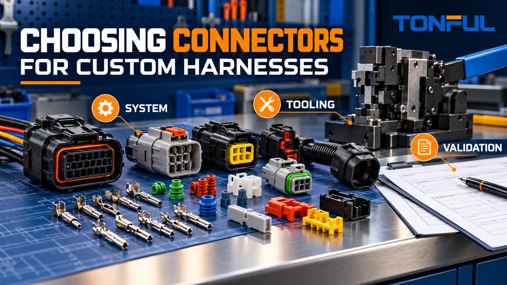
Choosing a connector for a custom harness means selecting a complete interconnection system, not just a plastic housing. The housing, mating half, terminals, wire seals, cavity plugs, secondary lock, backshell, tooling and approved wire range must work together. Two connectors can share the same cavity count and similar shape while differing in keying, terminal geometry, plating, sealing, current path or production tooling.
The sourcing decision also needs precise language. A genuine manufacturer part, an authorized-distribution part, a qualified alternative and an unverified look-alike are not equivalent evidence categories. This guide shows how to define the interface, compare candidate systems and approve alternatives without making unsupported interchangeability claims.
On this page: Requirements | System components | Genuine and alternatives | Terminals/tooling | Validation | Approval record
Define the Connector Requirements Before Selecting a Series
Start with the circuit and equipment interface. Record circuit count, voltage and current profile where applicable, signal type, grounding, wire sizes, shield or pair requirements and allowable temperature rise or voltage drop from the controlled specification. For communication or high-speed paths, define protocol, frequency/data-rate boundary, impedance and shielding requirements without assuming any connector with enough pins will work.
Next define the environment and mechanical use:
| Selection field | Questions to answer | Evidence source |
|---|---|---|
| Mating interface | Wire-to-wire, wire-to-board, panel or device? | Equipment drawing and mating part |
| Space/orientation | Envelope, pitch, exit direction and service access? | CAD and installation trial |
| Retention | Latch, CPA/secondary assurance, panel lock or hardware? | Manufacturer drawing/specification |
| Sealing | Unsealed, splash-exposed or application-defined ingress? | Exact series data and assembly test |
| Environment | Temperature, vibration, fluids, dust, UV or cleaning? | Customer/OEM qualification plan |
| Service | Mating frequency, field replacement and diagnostic access? | Maintenance requirement |
| Production | Volume, automation, repair and test-adapter needs? | Manufacturing plan |
Molex’s official connector mating fundamentals distinguish gender, polarization, keying and coding. Keying helps prevent incorrect mechanical mating, while coding can differentiate functionally different variants. These features must match both halves and the equipment architecture; color alone is not a reliable poka-yoke.
Use the exact connector drawing to define mating face, wire-entry face, latch, keys, cavity numbering, panel features and allowable orientation. TONFUL’s wire harness drawing and pinout guide illustrates why viewing direction must be confirmed before assigning circuits, although every connector series uses its own controlled documentation.
Select the Complete Connector System
A connector BOM should include all required elements, with full manufacturer part numbers and revision/status where relevant:
- Receptacle/plug or header housing.
- Female/male or tab/receptacle contacts as defined by the system.
- Wire seals, interface seals, mat seals and unused-cavity plugs.
- Secondary locks, terminal-position assurance or connector-position assurance devices.
- Backshells, boots, strain relief, panel hardware and protective caps.
- Approved extraction, insertion, crimp and assembly tooling.
- Mating connector or equipment-header reference.
Do not mix components from similar families unless the manufacturer documentation explicitly supports the combination. A terminal may physically enter a housing but lack the correct retention lance, seal interface or contact position. A cavity plug intended for another wire-seal family may not establish the required barrier. Secondary locks must fully engage with the selected terminals and cavity population.

Conceptual connector-system illustration—not an approved component combination. Use exact manufacturer part numbers and application documents.
For sealed assemblies, the connector rating alone does not prove the finished harness. Wire outside diameter, seal size, terminal crimp, plug population, cable exit, backshell, mating condition and assembly workmanship all influence performance. Define assembly-level testing from the project plan. The TONFUL waterproof cable connector guide provides application context, but exact connector evidence still controls.
Classify Genuine Parts and Alternatives by Evidence
Use terms that describe what is actually known:
| Category | Practical meaning | What it does not automatically prove |
|---|---|---|
| Manufacturer-branded part | Supplied under the connector manufacturer’s part number and controls | Correct project selection or authorized channel |
| Authorized-distribution part | Traceable purchase through an authorized channel | Fit/function unless the part number is correct |
| Customer-nominated part | Required by buyer drawing or approved list | Availability, cost or manufacturability |
| Qualified alternative | Candidate passed a defined equivalence and validation plan | Universal interchangeability across applications |
| Commercially compatible claim | Supplier claims mating or dimensional similarity | Material, plating, sealing, tooling or life equivalence |
| Unverified look-alike | Similar appearance or marketplace cross-reference | Any approved interchange relationship |
“OEM,” “original,” “same factory” and “equivalent quality” should not replace manufacturer identity, source traceability and technical evidence. Record the source of every claim. If a genuine part is mandatory, define whether the contract also requires authorized distribution, certificates, date/lot traceability or manufacturer packaging.
An alternative review begins with the released requirements, not the incumbent part’s appearance. Preserve samples and documentation for both candidates. Conditional approval should identify exact application, quantity, unresolved evidence, owner and expiry. An alternative approved for one wire size, seal and environment should not be expanded to all configurations without review.
Match Contacts, Wire and Application Tooling
Contact selection must match conductor material, size, stranding, insulation outside diameter, seal and current/signal function. Record contact finish and any application-specific plating requirement. Do not assume the largest wire that fits physically is within the terminal’s approved crimp range.
Tooling is part of the process definition. Molex’s application-tooling guidance states that proper interconnect-manufacturer tooling is important for standards and product warranty, and directs users to terminal-specific tooling documents. Use the exact contact form: loose-piece and reeled terminals may use different tools or applicators.
The process record should include terminal part number, wire/seal combination, tool/applicator and revision, die/cavity, setup, crimp-height or other controlled measurements, pull-test plan, inspection method and maintenance/calibration status. Generic hand pliers are not evidence of an approved crimp. TONFUL’s crimp pull-force testing guide explains how to document mechanical validation without inventing universal limits.

Conceptual process matrix. Contact, wire, seal and tooling combinations must follow the exact application specification.
Terminal insertion also requires control. Confirm orientation, insertion depth, audible/tactile cues where applicable, secondary-lock sequence and terminal retention. Avoid pulling wires as the sole check unless an approved procedure defines the method and force. Use connector-specific insertion/extraction tools to prevent housing or terminal damage.
Validate Form, Fit, Function, Process and Supply
An alternative-connector plan should compare five areas.
Form and mating interface
Measure envelope, keying, polarization, latch, panel features, cavity geometry, sealing surfaces and mating depth. Perform mating trials with the approved counterpart and check for forced engagement, partial locking or interference. A successful single mate is not endurance evidence.
Electrical and signal function
Confirm cavity assignment, contact system, current/voltage requirements, contact/path resistance method, temperature-rise conditions, insulation and dielectric requirements where applicable. For high-speed or sensitive signals, validate completed-channel performance, shield termination and pair geometry. The TONFUL impedance-matching guide explains why connector launches and assembly construction matter.
Mechanical and environmental performance
Define mating/unmating, terminal retention, connector retention, cable pull, vibration, temperature, fluids, sealing and other project-specific tests. Record sample allocation, conditioning, fixtures, parameters, failure criteria and acceptance source. Do not copy a test level from a different connector family.
Manufacturing process
Run production-intent stripping, seal loading, crimping, insertion, secondary locking, covering and electrical testing. Check tool access, error-proofing, inspection visibility, repair method and takt/capacity assumptions. Cross-section or destructive analysis is useful only with traceable samples and approved criteria.
Supply and change control
Compare source authorization, lead time assumptions, MOQ/minimum buy, lifecycle status, country/site, lot traceability, certificates, packaging and change-notification process. A cheaper connector can raise total cost if it requires new applicators, fixtures, validation, inventory separation or warranty containment. TONFUL’s wire harness BOM optimization guide provides a total-cost perspective.

Conceptual validation matrix. Approval applies only to the tested configuration and documented application scope.
Build a Sample and Release Plan
Allocate samples before testing. State whether independent groups cover electrical, mechanical and environmental tests or whether one sequence intentionally ages the same units. Keep unaged baseline samples where needed. Define destructive-analysis samples, invalid-test rules and replacement policy. The design authority should approve quantity and rationale.
First-article records should verify full part numbers, source, cavity population, contact/seal combination, tooling, dimensions, pinout, retention, workmanship and test results. Production controls should identify incoming verification, process setup, first-piece checks, electrical-test coverage, traceability and nonconformance reaction.
Do not broaden approval silently. A connector alternative approved with one wire, seal, mating half and environment is not necessarily approved for another gauge, unsealed variant, plating, cavity population or production site. Require change review before any controlled element changes.
Connector Selection and Alternative Approval Record
| Record field | Required entry |
|---|---|
| Application / circuit | Equipment, function and environment |
| Incumbent connector | Manufacturer, full part number and source |
| Candidate connector | Manufacturer, full part number and source |
| Complete component set | Housings, contacts, seals, locks and accessories |
| Wire/contact/tooling | Wire construction, seal, terminal, tool and setup |
| Mating interface | Counterpart, keying, latch, dimensions and result |
| Electrical evidence | Test method, conditions, results and acceptance source |
| Mechanical/environment | Samples, sequence, results and failure modes |
| Manufacturing trial | Process, inspection, test fixture and capacity |
| Supply evidence | Authorization, traceability, lifecycle and change control |
| Status | Verified / Conditional / Rejected / Not evaluated |
| Approval scope | Part, wire, seal, application, site and revision |
| Approver / date | Design, quality, manufacturing and procurement |
Discuss Harness Connector Selection With TONFUL
Send TONFUL the equipment interface, connector and mating references, circuit/pinout, wire and seal ranges, environment, qualification plan, volumes and source restrictions. TONFUL can review component compatibility, termination tooling, manufacturability, validation and supply assumptions against the controlled project. Final approval remains tied to exact part numbers and documented evidence.