
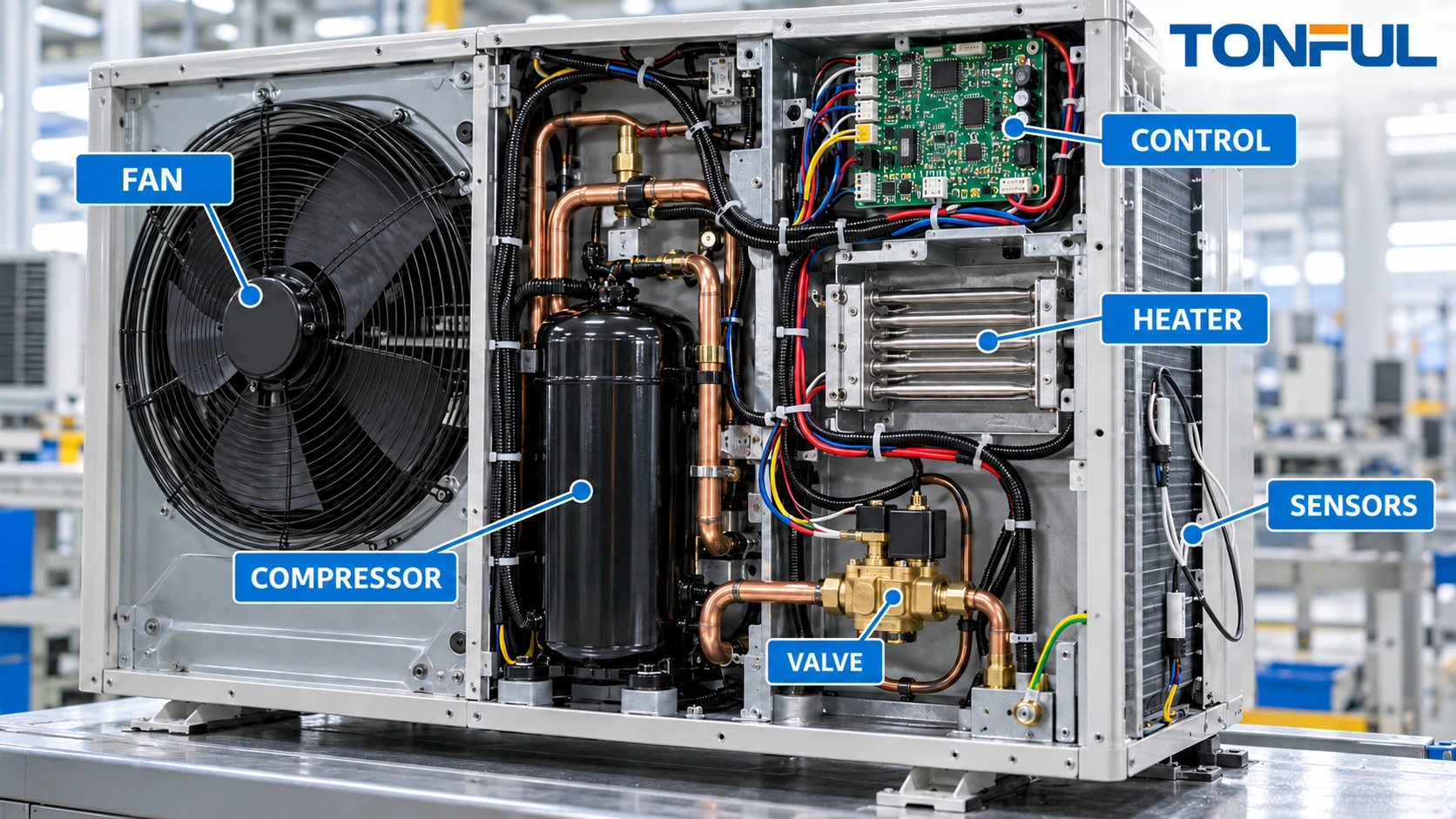
An HVAC wire harness can connect incoming power, compressors, indoor and outdoor fans, crankcase or supplemental heaters, valves, pressure and temperature sensors, condensate controls and electronic boards. These branches may operate at different voltages, currents, temperatures and control methods. They also share space with refrigerant tubing, sheet metal, water, airflow and service panels.
A reliable harness is not created by matching connector shells alone. Its specification must define each circuit, load state, conductor and terminal, environmental zone, mechanical route, assembly sequence and verification method. The completed HVAC equipment then requires separate safety, control, refrigerant-system and functional validation.
This guide covers custom harnesses within heat pumps, air conditioners, dehumidifiers, fan-coil units and related equipment. It does not provide universal conductor sizes, color codes, spacing, temperature ratings, test voltages or refrigerant requirements. Those inputs must come from the controlled equipment design, applicable standards, component data and approved validation plan.
Map Every HVAC Circuit and Operating State
Build a circuit schedule that links each source, protective device, switching element and load. Record normal operation plus relevant starting, stopping, defrost, emergency-heat, stalled, locked-rotor or fault states as assigned by the equipment program. A name such as “fan lead” is not enough if the same product family uses AC induction, electronically commutated or variable-speed motors.
| Circuit group | Information to define | Harness evidence |
|---|---|---|
| Compressor | Supply, phase, running and starting/locked condition, protector and switching path | Pinout, conductor/terminal record and load-path validation |
| Fan or blower | Motor type, speed-control method, feedback and service disconnect | Functional-state and connector-keying checks |
| Heater | Power, duty, switching, local temperature and protective devices | Hot-zone route and connection-temperature evidence |
| Valve or actuator | Coil voltage, polarity, suppression, duty and position feedback | Output-state and polarity verification |
| Temperature/pressure sensor | Sensor type, reference, range, polarity and noise sensitivity | Point-to-point and state/response test |
| Condensate device | Float, pump or switch logic; wet-zone boundary | Connector, routing and functional evidence |
| Control/communication | Board supply, encoded input, bus or low-voltage control | Cavity map, signal identity and system-level test |
| Protective bonding | Conductor, terminal, hardware, location and path | Bonding evidence under the equipment plan |
The TONFUL custom wire harness buying guide shows how circuit and branch data become a controlled purchasing specification. Never infer the allowable load from conductor diameter alone. Ambient temperature, bundling, insulation, duty, voltage drop, termination and enclosure airflow affect the released design.
Separate Compressor, Fan, Heater and Control Requirements
Compressor Power and Auxiliary Connections
Compressor circuits can experience conditions that differ substantially from steady running. Define the compressor type, supply architecture, contactor or drive interface, overload/protector arrangement and any crankcase-heater or sensor leads. Identify whether the harness carries direct compressor power, a contactor-coil request, inverter output or only a low-level command.
Do not apply line voltage to an unidentified cavity or assume every terminal in a nominal mains-powered unit carries mains potential. Variable-speed systems may combine power electronics, low-voltage communication and sensor interfaces. The approved electrical diagram and component documentation must control probing and bench energization.
Terminals, disconnects and connectors require evidence for the selected conductor, load, mating interface and temperature. Routing must prevent compressor movement or service handling from loading the crimp or contact. If a terminal cover, strain relief or routing clip is part of the protective system, include it in the controlled BOM and assembly record.
Fan and Blower Branches
HVAC fans may use tapped-speed motors, capacitor circuits, electronically commutated motors or networked drives. Record every winding, capacitor, speed request, feedback and protective function. A connector with the same number of cavities can still be incompatible if speed taps, polarity, feedback or communication differ.
Harness geometry should support motor removal without pulling on wires while keeping branches clear of blades, belts, dampers and blower housings. Where airflow causes repeated movement, define support spacing, flex location and abrasion protection from the actual equipment layout rather than a generic rule.
Electric Heaters and Defrost Circuits
Supplemental heaters, defrost heaters and crankcase heaters create localized temperature and switching demands. Establish the expected temperature at terminals, housings, wire and nearby sleeves under the project test conditions. A cooler wire segment elsewhere in the cabinet does not prove the interface is acceptable.
Protective devices such as thermal cutoffs, thermostats or limit switches must be identified by function and position. Their leads and connections should not be rearranged as ordinary splices. Show released routing relative to heater elements, insulation, refrigerant lines, plastic parts and airflow.
Sensors, Valves and Low-Voltage Controls
Temperature, pressure, humidity, current, flow and condensate sensors may use resistance, voltage, frequency, communication or dry-contact outputs. Define the sensor reference, polarity, pinout and expected state behavior. If pairing, shielding or separation is needed, draw it and specify termination details.
Reversing valves, expansion valves, dampers and condensate pumps require their own coil, drive or feedback definitions. The harness test may verify continuity, polarity or a controlled component state, but it does not prove refrigerant flow, valve capacity or complete control logic.

<figcaption><em>A function-based circuit map prevents high-load branches and low-level controls from being treated as interchangeable wiring.</em></figcaption>
Design for HVAC Environmental Zones
Divide the equipment into zones before selecting materials and protection. Outdoor sections may see solar heating, rain paths, condensation, freezing conditions, dust and service chemicals. Indoor coils and drain pans introduce condensate. Compressor and heater compartments add heat and vibration. Refrigerant lines can be hot, cold or wet and may move during operation.
For each branch, document:
- Normal and abnormal local temperature.
- Condensation, splash, drain-pan or outdoor exposure.
- Refrigerant/oil and cleaning-chemical contact risk.
- Vibration, compressor motion and airflow-driven movement.
- Proximity to tubing, fins, sharp sheet metal and moving parts.
- Entry points, grommets, glands, clips and strain relief.
- Service-panel removal and component replacement path.
The route must prevent damaging contact with refrigerant tubing unless the controlled equipment design specifically manages that interface. Sleeving or tape cannot compensate for an undefined route. The wire harness protection methods guide can help distinguish abrasion, heat, fluid and strain-relief functions.
Where a connection sits in a wet or condensing zone, evaluate the complete connector assembly, wire seal, cavity plug, rear seal, mating half and installation process. An individual “waterproof” component does not prove the finished interface remains sealed after crimping, mating, routing and environmental conditioning. TONFUL’s waterproof cable assembly guide explains this assembly-level boundary.
Control Connectors, Terminals and Wire Materials
Specify housing, contact, seal, secondary lock, mating device, wire range, plating and applicator for every interface. Similar housings may accept multiple contact variants. An alternative contact or connector requires controlled technical comparison and validation, not only a fit check.
Wire insulation and jacket selection should follow actual temperature, moisture, chemical, flex and termination conditions. Material families such as PVC, silicone and fluoropolymer constructions can support different needs, but the exact wire specification governs. Use TONFUL’s PVC, silicone and PTFE wire comparison as a selection framework, not as a source of universal ratings.
For field-service connectors, consider latch access, keying, mating cycles and diagnostic probing. Avoid coarse test probes that spread terminals or puncturing seals unless an approved repair method controls restoration. Connector photographs should use a consistent end-view direction and remain linked to the released revision.
Verify Routing, Assembly and Service Access
Harness drawings should establish equipment datums, branch origins, breakout lengths, connector orientation, clip positions and tolerances. Verify the actual manufacturing sequence: cabinet, coil, compressor, fan deck, drain pan, insulation, panels and controls may be installed in different orders.
A branch can fit the completed CAD model but remain impossible to connect on the line. Conduct production-intent trials that include tool access, latch engagement, routing through openings and panel closure. The wire harness DFM checklist provides practical checks for service loops, branch geometry and assembly access.
Prevent cross-connection through keying, connector differentiation, labels and controlled branch reach. Do not use harmful tension as a poka-yoke. Verify that service loops cannot enter fan blades, contact hot tubing or become trapped under panels. Retention clips must match the panel hole, edge or stud and remain secure under the defined vibration and temperature conditions.

<figcaption><em>Production-intent routing inspection checks tubing clearance, condensate zones, moving equipment, sharp edges and service-panel access.</em></figcaption>
Create Separate Harness and Equipment Validation Plans
Harness production testing starts with a released netlist. Verify continuity, open/short conditions, cavity mapping and connector orientation. Add resistance, component-state, polarity, insulation-resistance or dielectric tests only when required by controlled documentation. The continuity, insulation resistance and hi-pot testing guide explains why these methods answer different questions.
The official IEC 60335-2-40:2024 addresses safety requirements for electric heat pumps, air conditioners, dehumidifiers and related units within its scope. It is equipment-level context; it does not certify an individual harness or supply universal wire, terminal, routing or test limits for every HVAC project.
Equipment validation may include temperature, moisture, abnormal operation, mechanical strength, protective bonding, dielectric behavior, EMC, control-function and refrigerant-system requirements. Assign ownership, sample allocation, powered state, monitoring and acceptance source. Component or harness approval alone cannot establish complete-unit compliance.
Sample Allocation and Failure Records
Define whether independent sample groups or sequential conditioning will be used. Record an unconditioned reference when required. Allocate destructive-analysis samples before testing and define rules for invalid tests, replacement samples and retest. The responsible equipment program must approve the quantity and rationale.
For every result, record harness part/revision, equipment configuration, sample ID, material lots, fixture, instrument status, test condition, raw result, limit source, decision, reviewer and date. Preserve the as-found routing after failure. Distinguish primary electrical or mechanical damage from secondary heating, moisture or abrasion.
Production Control and Change Management
Receiving inspection should verify exact wire, terminals, housings, seals, clips, sleeves and labels. Process controls should cover cutting, stripping, crimping, splicing, seal placement, component insertion, routing and electrical test. First-off checks are important after applicator change, maintenance, material change, program update or restart.
Changes to compressor/fan type, heater load, control board, connector source, wire construction, refrigerant routing, cabinet geometry or test program may affect the harness. Require impact review, approval, effectivity and revalidation. Lot genealogy should connect shipped assemblies with material, process and test records.
Copyable HVAC Harness Specification Record
| Field | Required entry |
|---|---|
| Equipment scope | Unit type, model, market, revision and electrical architecture |
| Circuit/load map | Source, destination, state, protection and switching method |
| Environment zones | Temperature, condensate, outdoor exposure, chemicals and vibration |
| Wire/cable | Controlled part, conductor, insulation/jacket and identification |
| Interfaces | Housing, contact, seal, mating half, keying and service access |
| Geometry | Datums, branches, clips, grommets, tolerances and service loops |
| Refrigerant-system boundary | Tubing clearance, movement and leak-detection interface if applicable |
| Harness tests | Netlist and project-defined electrical/component checks |
| Equipment validation | Owner, samples, conditions, monitoring and acceptance source |
| Change control | Notification, effectivity, revalidation and traceability |

<figcaption><em>A shared specification record aligns equipment engineering, harness manufacturing, assembly and final HVAC validation.</em></figcaption>
Final Release Checklist
- Compressor, fan, heater, valve, sensor, control and bonding circuits are mapped.
- Starting, stalled, defrost and other assigned operating states are documented.
- Local heat, condensate, outdoor exposure and movement zones are defined.
- Connector end views, cavities, contacts and mating halves are controlled.
- Routing protects against tubing, fins, edges, fans, heaters and panel pinch points.
- Assembly and authorized service access are verified on production-intent equipment.
- Harness tests and complete-unit validation have separate scope and owners.
- Sample allocation, limits and failure criteria are approved before testing.
- Production genealogy supports material, process, test and shipment traceability.
- Changes receive documented impact review and effectivity control.
Develop HVAC Wire Harness Assemblies With TONFUL
For an HVAC harness quotation, provide TONFUL with the unit architecture, circuit/load schedule, drawings, BOM, connector interfaces, environmental zones, refrigerant and mechanical boundaries, assembly sequence, test plan, demand and applicable requirements. TONFUL can review manufacturability, component control, sample records and production testing within the documented project. Final equipment safety, EMC, refrigerant-system performance, controls and market approval remain responsibilities of the complete HVAC program.