
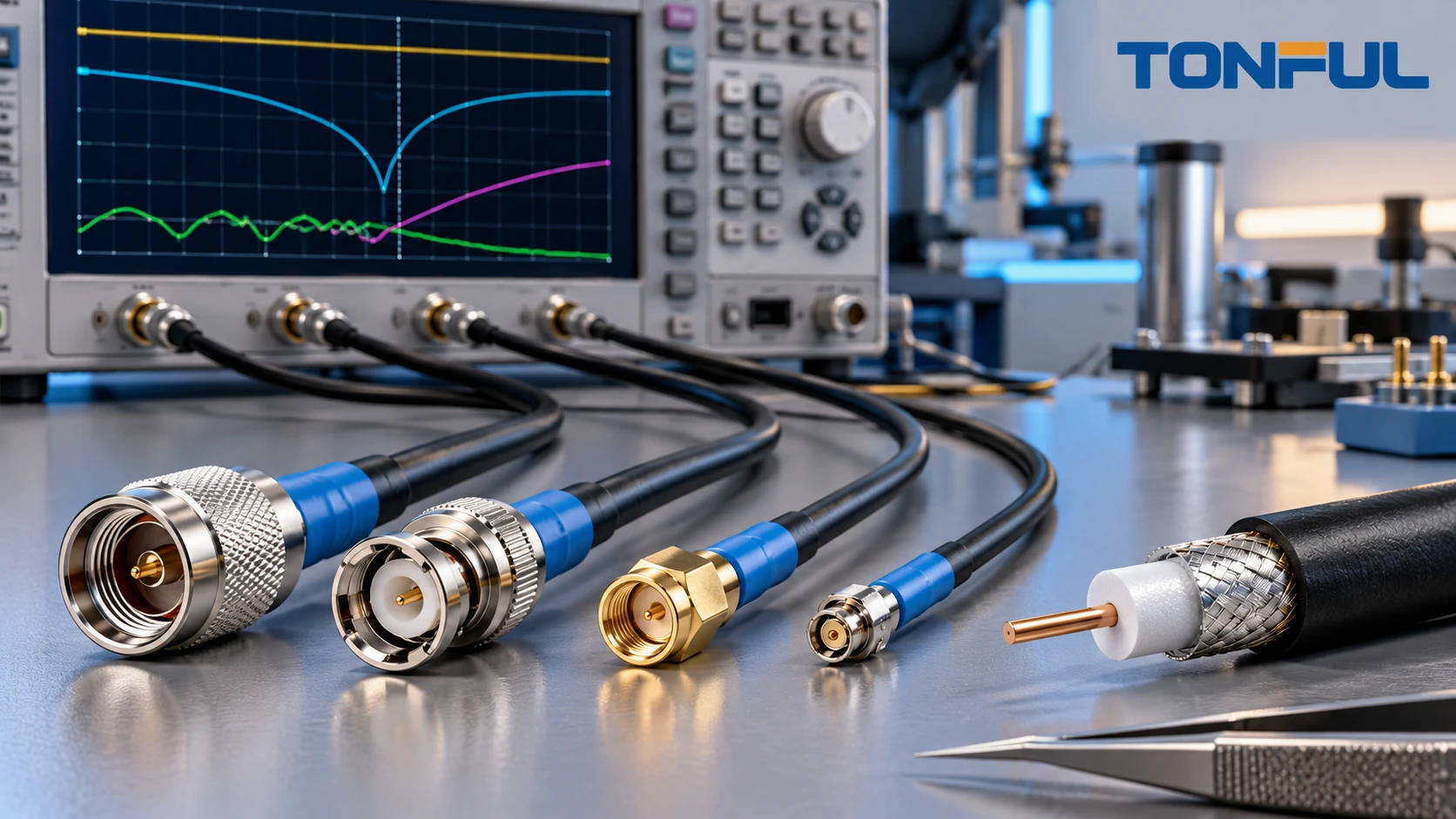
Custom coaxial cable assemblies carry RF, video, timing or measurement signals through a concentric transmission structure. Their performance depends on the center conductor, dielectric, shield, jacket, connector transition and mating interface acting as one controlled path. A cable can pass continuity while still producing unacceptable reflection or loss at the operating frequency.
The RF specification should begin with the system function and frequency range, then define target impedance, connector interfaces, cable construction, length, routing, environment and measurable acceptance criteria. A connector name alone does not establish complete assembly performance, and a supplier’s component rating does not automatically apply after termination to a different cable.
This guide addresses passive flexible, conformable and semi-rigid coaxial cable assemblies. Active RF modules, antenna assemblies and multi-channel products require additional system-level controls.
Define the Electrical Mission First
Record signal type, operating and test frequency range, target impedance, source/load interfaces, allowable loss and reflection, power level, shielding needs and environmental location. Identify whether phase, time delay or amplitude matching matters between multiple assemblies. If the assembly belongs to a calibrated measurement setup, define whether it is part of the fixture, reference plane or delivered product.
Also identify the consequence of degradation. A short internal receiver jumper, an antenna feed, a high-power transmitter lead and a laboratory reference cable may use similar-looking coax while carrying very different risks. Document duty cycle, nearby heat sources, enclosure grounding, mating frequency and service access. These application inputs determine whether the buyer needs basic production screening, full swept data for each unit, matched-set records or additional environmental correlation. They also prevent an attractive general-purpose cable from being approved outside its evidence.
The official TE RF cable assemblies portfolio separates coaxial products by connector system, frequency/application and performance needs. It supports a key sourcing principle: connector family, cable and frequency range must be selected together. The project drawing and approved test plan still control the actual assembly.
Use a custom cable assembly buying guide for commercial and general mechanical fields, then add RF-specific requirements:
- Target characteristic impedance and tolerance source.
- Operating and verification frequency ranges.
- Maximum insertion loss and return-loss/VSWR criterion.
- Connector interface, sex, orientation and coupling style.
- Cable construction, shield and bend limits.
- Electrical length, phase or delay matching where required.
- Calibration method, reference planes and fixture treatment.
Match Cable, Connector and Impedance
Coaxial cable geometry establishes a transmission path through the relationship among center conductor, dielectric and outer conductor. The connector must maintain a compatible transition. Do not mix nominal impedance families or assume that a mechanically mateable adapter preserves the required RF behavior.
Select cable using frequency-dependent attenuation, diameter, flexibility, bend durability, shielding, power handling, temperature and environmental exposure. Small cable can improve packaging while increasing loss or fragility. Larger cable can reduce loss but increase bend load on miniature connectors. Semi-rigid construction offers stable geometry but requires controlled forming and may be unsuitable for repeated flexing.
| Selection field | Cable evidence | Connector evidence | Assembly evidence |
|---|---|---|---|
| Impedance | Cable datasheet/drawing | Interface specification | Measured reflection result |
| Frequency | Attenuation and mode limits | Connector frequency scope | Swept RF test range |
| Mechanical fit | OD, dielectric and shield dimensions | Compatible cable range | Termination inspection |
| Environment | Jacket and material data | Plating/seal data | Conditioned assembly result |
| Flex/routing | Bend and flex guidance | Cable-exit geometry | Installed sample review |
The connector selection guide applies here with extra rigor: connector body, center contact, ferrule, cable preparation, tooling and mating interface form a qualified set.
Specify Both Connector Ends Completely
For each end, record manufacturer, full part number, interface family, plug/jack or male/female designation, straight/right-angle orientation, coupling method, panel/bulkhead requirements and mating reference. Include torque only when the controlled connector documentation or project specification requires it.
Connector terminology can be confusing because body style and center-contact sex do not always align with casual descriptions. Use manufacturer drawings and include a clear photograph or end view. If reverse-polarity or keyed variants exist, state the exact interface rather than relying on a family name.
Right-angle connectors alter routing and may introduce a different transition than straight connectors. Define clocking relative to labels, panel flats or another datum. For bulkhead ends, specify panel thickness, hardware stack, orientation and grounding boundary.
Control the Connector Launch and Termination
RF performance is especially sensitive where coax geometry opens for termination. Strip lengths, dielectric exposure, center-conductor position, braid handling, ferrule placement and solder quantity must follow the approved connector/cable application process. Excess exposed dielectric or a distorted shield transition can create a local impedance discontinuity.

Conceptual coaxial termination cutaway identifying controlled features; it is not an acceptance standard, laboratory cross-section or measured RF model.
Depending on design, termination may use crimp, solder, clamp, compression or other controlled methods. The work instruction should state cable preparation dimensions, tooling, center-contact attachment, inspection points, body assembly and required verification. Do not combine a connector with an unlisted cable merely because the cable OD fits the ferrule.
Inspect for damaged center conductor, nicked dielectric, loose braid strands, incomplete shield capture, cold or excessive solder, deformed ferrule, contamination and incorrect body assembly. When destructive sectioning is used for process qualification, retain sample identity and section location; a conceptual image cannot replace traceable evidence.
Define Length, Phase and Routing Correctly
Mechanical length can be measured between connector reference planes, body shoulders or cable cut points. State the exact datum, finished tolerance and connector orientation. For right-angle or bulkhead assemblies, add clocking and panel reference.
Electrical length, propagation delay and phase are not interchangeable with mechanical length. If matched assemblies are required, define the frequency, reference temperature, matching method, maximum mismatch and whether connectors are included. Avoid generic “phase matched” language without a measurable criterion.
Routing should respect the approved bend radius, flex zone, torsion and support. A tight cable tie can deform the dielectric and shield. Unsupported connector exits can concentrate bending at the termination. Review the installed equipment path using the same DFM approach applied to wire harness routing and service loops.
Separate DC Checks From RF Performance Tests
Continuity and shorts testing can verify the center conductor and shield paths, but it cannot prove RF performance. A coax assembly may have correct continuity yet show excessive reflection, insertion loss or instability under flex.
| Test | Primary purpose | Controlled conditions |
|---|---|---|
| Center/shield continuity | Detect opens and basic path errors | Fixture contacts and resistance threshold source |
| Center-to-shield isolation | Detect unintended shorts/leakage | Test method and voltage appropriate to assembly |
| Return loss or VSWR | Evaluate reflections | Frequency sweep, calibration and reference planes |
| Insertion loss | Evaluate transmission loss | Frequency sweep, fixture and cable length |
| Time-domain measurement | Locate/characterize discontinuities when specified | Instrument setup and interpretation method |
| Phase/delay | Compare electrical length | Frequency, temperature and matching rule |
| Mechanical/environmental | Verify stability after defined stress | Sample allocation, sequence and acceptance source |
The continuity, insulation-resistance and hi-pot guide explains the boundaries of basic cable tests. Hi-pot or insulation resistance should be used only when the controlled design requires it and the method is compatible with the assembly.
Build a Reproducible Network Analyzer Test
An RF result is meaningful only with a controlled measurement setup. Record instrument model, frequency range, calibration type, calibration kit, cable/adapter fixtures, reference planes, port extension or de-embedding, test power, IF bandwidth where relevant, ambient condition and software revision. Save raw traces or data files, not only a screenshot marked pass.

Conceptual RF test setup showing calibration and reference-plane controls; project requirements define the instrument configuration and limits.
Define how adapters are handled. An adapter included between the calibration plane and device under test contributes to the measured result unless removed mathematically through an approved method. Reference cables and fixtures wear, so include inspection, verification and replacement rules.
For production, a full swept test may be required on every unit, sampled, or replaced by another validated screen depending on risk and contract. Do not infer a universal sampling plan. Qualification should establish design capability; production testing should detect manufacturing escapes; first-article inspection should verify the released configuration.
Plan Mechanical and Environmental Validation
Where required, validate mating retention, cable pull, bend/flex, vibration, shock, temperature, humidity, corrosion or ingress using project-specific conditions. Record whether the same samples undergo sequential stresses, whether unaged controls are retained and which tests are destructive. Define invalid-test and replacement-sample rules before execution.
Compare RF results before and after conditioning. A connector can remain electrically continuous while return loss or insertion loss degrades. Preserve failure location, photographs, raw traces and teardown evidence. Separate fixture failure from sample failure through documented investigation rather than automatic retest.
Use a Complete Assembly Record
| Record field | Required entry |
|---|---|
| Identity | Assembly number, revision, lot and sample ID |
| RF definition | Impedance, frequency range and acceptance metrics |
| Cable | Manufacturer part, construction, lot and finished length |
| Connectors | End A/B parts, orientation, interfaces and mating references |
| Process | Strip setup, tooling, solder/crimp controls and operator/machine |
| Visual/dimensional | Launch, ferrule, orientation, length and workmanship |
| DC result | Continuity, shorts and conditional isolation tests |
| RF result | Calibration, reference planes, traces and pass/fail |
| Conditioning | Sequence, sample allocation and before/after change |
| Disposition | Acceptance source, deviation, reviewer and date |
Changes to cable supplier, dielectric, shield, connector/contact, plating, termination dimensions, tooling, solder process, length, routing or test fixture can affect RF performance. Route them through revision control and lot traceability and repeat the level of validation justified by risk.
RFQ and Release Checklist

A controlled coaxial assembly record aligns mechanical construction with measurable RF acceptance evidence.
Provide:
- Application, signal role, target impedance and frequency range.
- Allowable insertion loss, reflection and phase/delay criteria where applicable.
- Cable manufacturer part number and environmental requirements.
- End A/B connector parts, interface sex, orientation and mating references.
- Length datums, tolerances, clocking, labels and routing constraints.
- Cable preparation, termination tooling and workmanship requirements.
- DC, RF, mechanical and environmental test plans.
- Calibration, fixtures, reference planes and retained data requirements.
- First-article sample quantity and installed-interface review.
- Traceability, packaging, change notification and deviation rules.
- Forecast, order quantity, tooling/NRE ownership and release schedule.
TONFUL can review a controlled coaxial cable assembly package for component compatibility, termination feasibility, dimensions, routing and test-record requirements. Send the cable and connector documentation, RF performance targets, mechanical drawing and validation plan for project-specific sample and quotation review. Final ratings and RF claims must remain limited to the approved configuration and measured evidence.
—