
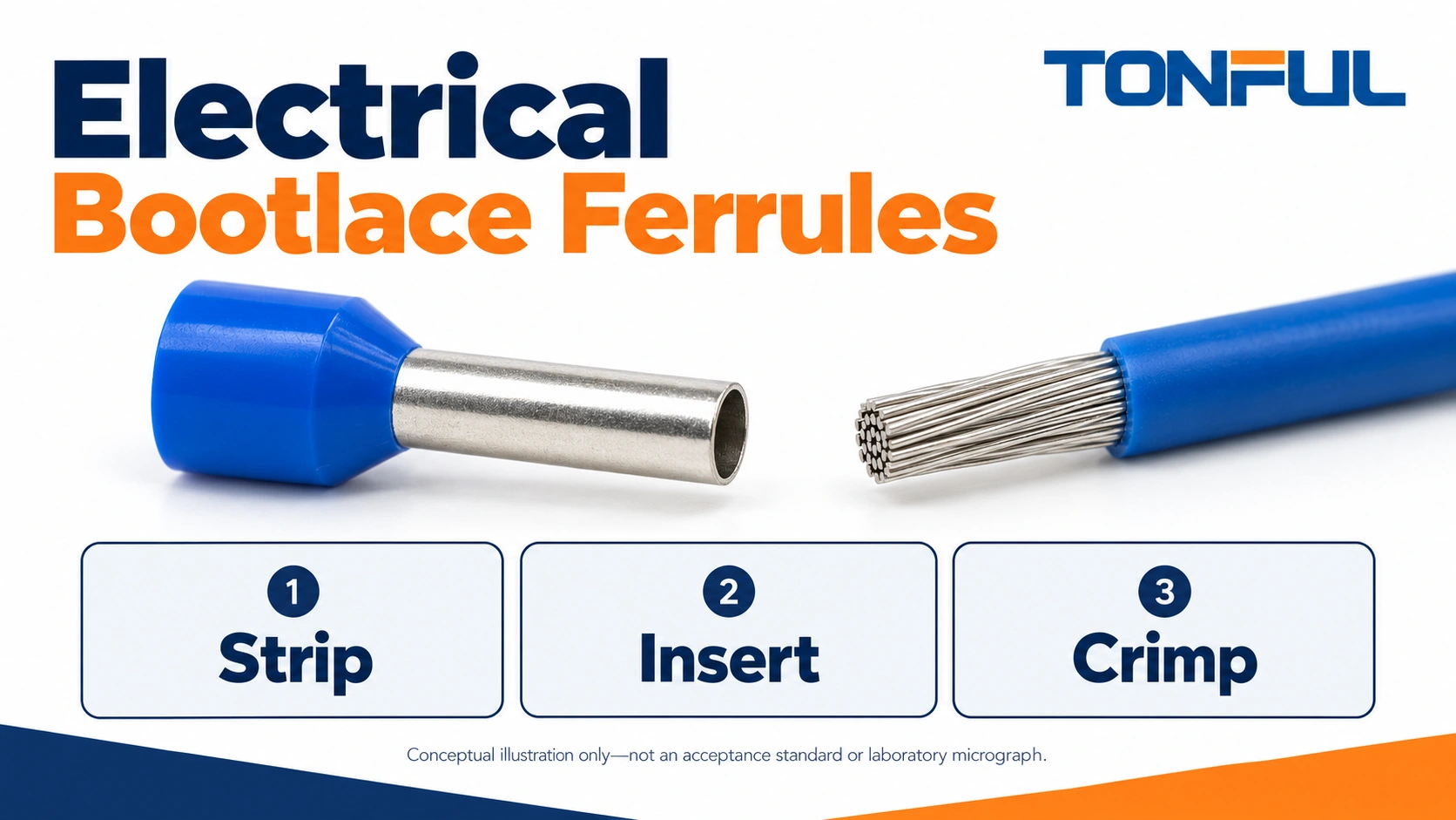
Electrical bootlace ferrules gather the strands of a flexible conductor inside a thin metal sleeve before that conductor enters a compatible terminal. Installing one is not simply squeezing a colored tube. The wire, ferrule, crimping tool and receiving terminal must work together, and the finished connection must remain within the receiving equipment’s instructions.
This guide concerns electrical cord end terminals, not shoelace aglets. Use it to prepare a work instruction, supervise first-piece checks or diagnose an assembly that will not fit. It does not replace the ferrule drawing, tool instructions or equipment manufacturer’s wiring requirements.
Jump to: Compatibility · Stripping · Insertion · Crimping · Inspection · Release record
Compatibility: Check the Complete Termination Before Cutting
Match the wire and receiving terminal
Begin with the conductor specification: material, nominal cross-sectional area, strand construction and insulation outside diameter. A ferrule selected by insulation color or approximate bundle diameter can be wrong even when it slides over the wire. The sleeve must be specified for the actual conductor construction and size.
Next, check whether the receiving screw, cage or spring terminal accepts ferruled conductors. Some equipment accepts bare stranded wire directly; other designs publish different conductor ranges for ferruled and unferruled wires. A ferrule does not expand the permitted range or make an incompatible conductor acceptable.
For sourcing, distinguish single-wire, twin and bare constructions in TONFUL’s cord end terminal range. That page identifies the product family, but the selected part drawing still governs dimensions. A plastic collar guides insertion; it is not a substitute for an insulated enclosure or a waterproof seal. Weidmüller’s ferrule intended-use guidance also distinguishes the collar’s insertion function from mechanical insulation support or kink protection and emphasizes careful conductor preparation and a suitable crimp profile. Apply the selected product and equipment instructions rather than transferring its numeric examples to every ferrule.
| Setup item | Information to obtain | Decision before assembly |
|---|---|---|
| Wire | Material, size, strand class, insulation diameter | Confirm compatibility with ferrule and equipment |
| Ferrule | Part number, metal sleeve length, entry geometry | Confirm the clamping zone receives metal sleeve |
| Tool | Approved profile, range, cavity or adjustment | Confirm it covers this exact combination |
| Equipment | Conductor range, insertion depth, torque if applicable | Confirm ferrules are permitted |
| Work instruction | Revision and inspection criteria | Stop if acceptance instructions conflict |
Establish a safe work boundary
Prepare conductors away from energized equipment. Isolate supplies, address stored energy and follow the site’s lockout and verification procedure before installation. In the United States, OSHA’s electrical work-practice requirements describe deenergizing and verification responsibilities. Only qualified personnel should perform the applicable electrical work. A ferrule collar does not make live work safe.
Stripping: Expose the Required Length Without Damaging Strands
Set length from the approved combination
Use the ferrule and receiving-terminal instructions to establish the stripping length. Metal sleeve length, required conductor position and terminal insertion depth are related but are not interchangeable dimensions. Do not copy a stripping value from a different ferrule merely because its collar has the same color.
Make a setup sample before processing the production wire. After stripping, compare the exposed conductor against the work instruction and check that the insulation ends at the intended position near the sleeve entry. Too little exposed conductor can leave insulation beneath the crimping zone. Too much can leave unintended bare copper outside the protected connection.
Use a stripping tool suitable for the insulation and strand construction. Adjust it on representative material, not on a leftover cable of uncertain identity. Inspect for missing strands, nicks, scoring and stretched insulation. If a conductor is damaged, cut back to sound material when the remaining length permits; do not hide the damage inside a ferrule.
Keep the bundle intact
Handle the stripped end gently. Preserve the original strand lay rather than aggressively twisting the bundle into a hard point. Do not trim individual strands to force a conductor into an undersized sleeve. Do not tin the end unless the complete termination process explicitly requires and permits that treatment.
Record changes in insulation behavior. A stripping setup that worked on one wire lot may produce different results after a supplier, material or tool-blade change. Recheck the first piece after those changes rather than waiting for a terminal insertion problem downstream.

Insertion: Put Every Strand Inside the Metal Sleeve
Load the conductor without force
Guide the intact conductor bundle through the ferrule entry until the insulation and conductor reach their specified positions. No strand should fold backward outside the sleeve or remain trapped between the collar and wire insulation. Inspect from more than one direction because a strand can be hidden behind the wire.
Unexpected resistance is a reason to stop. Check whether the conductor size is wrong, the stripped end is distorted, the sleeve is damaged or the selected ferrule has an unsuitable entry. Do not solve a mismatch by shaving insulation, cutting strands or enlarging the sleeve with an improvised tool.
The finished conductor position at the sleeve tip must match the relevant instructions. Avoid a universal rule that copper must always protrude, or must never be visible. The equipment geometry and specified preparation determine what is acceptable. Keep photographs of approved samples with their drawing revision so operators know which feature they are comparing.
Treat twin ferrules as a separate setup
Two wires require a ferrule explicitly intended for that combination and a receiving terminal that permits it. Do not assume a single-wire ferrule can accept two smaller conductors just because their nominal areas add up. Collar geometry, strand packing, tool coverage and equipment approval still matter.
Prepare both conductors to the approved length and insert them together without allowing one to retreat. Confirm each wire is present and fully seated before crimping. Where separate service isolation or circuit identification is needed, engineering may prefer two terminals rather than combining wires at one point.
Crimping Electrical Bootlace Ferrules With the Specified Tool
Choose the profile for the terminal, not appearance
Square, hexagonal and other profiles produce different finished envelopes. A neat-looking profile may still be too wide for the terminal entry or incompatible with the intended clamping arrangement. Select the ferrule-tool-terminal combination from the applicable instructions, then verify insertion with a setup sample.
TONFUL’s crimping-tool information can support a tooling inquiry, but a general tool range is not evidence that every cavity works with every ferrule. Provide the ferrule part number, wire construction and required finished profile when requesting a recommendation.
Position the metal sleeve in the tool as instructed, keeping the plastic collar outside the active compression zone unless the tool instructions explicitly show otherwise. Hold the conductor fully seated and complete the prescribed cycle. Do not interrupt a controlled-cycle tool halfway or apply additional overlapping crimps to improve an uncertain result without an approved procedure.
Ordinary pliers, side cutters and a vise are not substitutes for specified crimp tooling. They can create local damage without controlling compression around the conductor. If the proper tool is unavailable, hold the work rather than releasing a connection based on a hand tug.
Verify fit without modifying the finished end
After crimping, check the finished profile and the terminal entry on a deenergized setup. Do not flatten, hammer, file or cut a crimped sleeve to make it fit. A fit problem can reveal an incorrect profile, an oversized ferrule or an unsuitable receiving terminal.
Keep ferrules distinct from ring lugs and other non-insulated terminal designs. Their connection interfaces and tooling requirements are different. A die that forms a satisfactory ring-terminal barrel is not automatically suitable for a thin ferrule sleeve.
Inspection: Separate Visual Screening From Acceptance Evidence
Use a repeatable visual sequence
Inspect the wire entry, sleeve body and sleeve tip before installing the conductor. Look for escaped strands, displaced insulation, split metal, severe distortion and a damaged collar. Compare dimensions or conductor position only against the controlled criteria for the selected part.
| Observation | Immediate disposition | What to investigate |
|---|---|---|
| Strand outside sleeve | Hold and remake as permitted | Insertion technique, wire size, strip quality |
| Split sleeve | Hold affected pieces | Ferrule identity, tool setting, damaged tooling |
| Collar crushed in crimp zone | Hold for review | Tool placement and ferrule positioning |
| Wire retreats during crimping | Hold and inspect setup | Strip length, insertion method, operator support |
| Crimp will not enter terminal | Do not modify the end | Profile, finished envelope, terminal range |
| Insulation enters metal compression zone | Hold for approved disposition | Strip length and seating position |
A light handling check may identify gross looseness, but it is not a quantified pull test and does not prove electrical or environmental performance. If the control plan requires destructive testing, use its sample quantity, equipment, method and acceptance source. Do not return a destructively tested sample to service.
Install and inspect the receiving connection
Insert the ferruled conductor to the equipment’s specified depth. Tighten screw terminals to the equipment instruction where torque applies, using the required tool and procedure. Spring terminals have their own actuation and seating checks; do not invent a torque step for them.
Check for exposed conductive material outside the intended enclosure, wire strain and interference with neighboring connections. Routing must not pull the ferrule sideways or transfer repeated bending to the sleeve exit. Standard nylon-insulated terminals are a different product family, not a cure for an unsuitable ferrule installation.

Release Record: Make the Installation Reproducible
Capture the setup and reaction plan
Use the following compact record as an editorial template, not as an acceptance standard. Attach the actual limits and photographs from approved documents. The record should let another person reproduce the setup without guessing which wire, sleeve or tool was used.
| Record field | Entry required |
|---|---|
| Job and circuit | Assembly revision and connection identifier |
| Materials | Wire identity and lot; ferrule part and lot |
| Tool setup | Tool ID, cavity/profile, condition check |
| Preparation | Approved strip length and instruction revision |
| First-piece result | Strand condition, seating, crimp appearance, terminal fit |
| Additional verification | Required method, sample IDs and acceptance document |
| Release | Inspector, date and approved disposition |
Define when to repeat first-piece verification: a different ferrule or wire lot, tooling change, maintenance, setup adjustment or restart requiring review under the control plan. If defects appear, identify the last accepted check and contain the potentially affected work. Fixing the next piece does not establish that the previous pieces are acceptable.
Send a useful ferrule inquiry
For a new application, send TONFUL the conductor specification, receiving-terminal identification, required sleeve length, approved profile and expected assembly method. Request the exact part drawing and compatible tooling information through its wire-terminal sourcing team. Include a sample-review plan when fit is tight or multiple conductors are proposed. That information supports a meaningful recommendation without treating a product-family description as proof of application approval.