
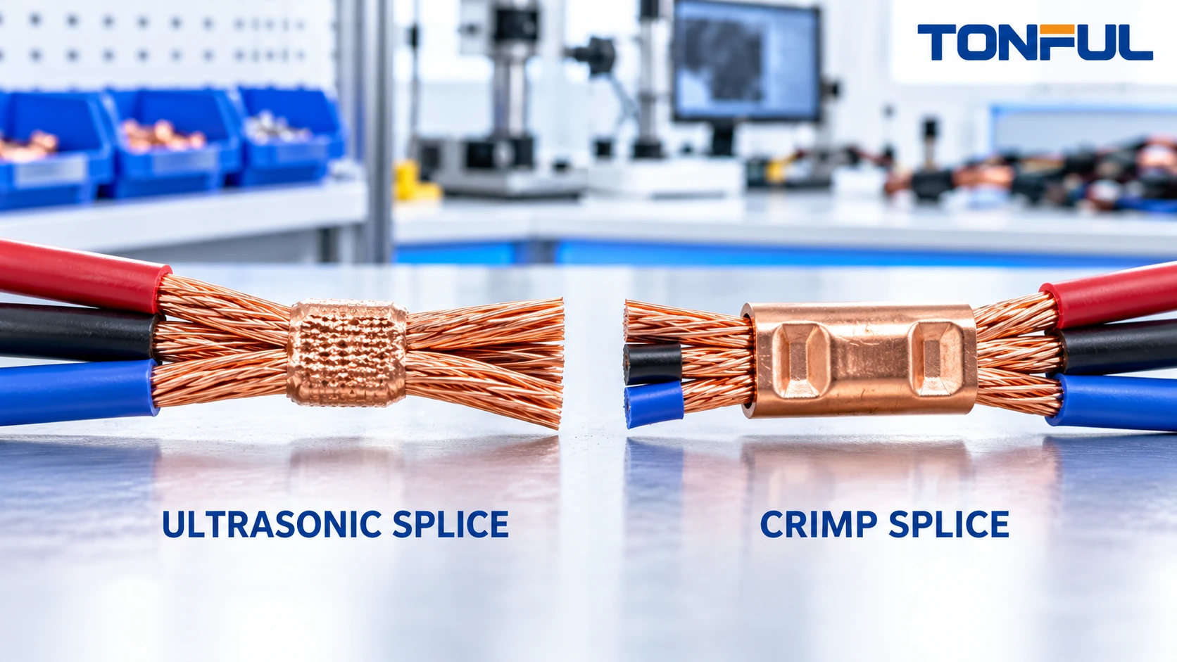
A branch splice is not just a way to join copper. It determines bundle diameter, branch direction, tooling, inspection access, covering, repair strategy and the evidence needed to release a wire harness. Ultrasonic wire splicing and mechanical crimp splicing can both produce dependable joints, but neither is automatically superior for every conductor combination or production environment.
The correct choice begins with the controlled drawing: conductor material and plating, strand construction, cross-sectional area, branch count, current path, splice location, environmental exposure and acceptance source. It ends with process qualification and production records for the exact combination. Connector appearance, one successful sample or a machine supplier’s broad capability range is not enough.
This guide compares the two processes for multi-branch harnesses. It does not provide universal weld energy, amplitude, pressure, crimp height, pull force, resistance or current limits. Those values must come from the approved equipment study, splice drawing, component documentation, customer specification and validation plan.
Quick Process Comparison
| Decision area | Ultrasonic wire splice | Crimp splice | Required project evidence |
|---|---|---|---|
| Joint formation | Solid-state bonding created by controlled vibration, force and tooling | Barrel mechanically compressed around conductors with matched tooling | Approved construction and process window |
| Added component | Normally no splice barrel | Requires specified barrel or splice terminal | Bill of material and lot traceability |
| Package shape | Can create a compact welded nugget | Shape follows barrel and insulation/support design | Envelope drawing and harness-board trial |
| Conductor sensitivity | Material, plating, strand lay, cleanliness and stack orientation matter | Barrel range, conductor-area combination, strip and insertion matter | Exact wire list and approved combination |
| In-process monitoring | Equipment may record energy, time, displacement, force or related signatures | Crimp-force monitoring and dimensional checks may be available | Validated monitoring limits and reaction plan |
| Destructive evidence | Pull/peel, cross-section and electrical tests as specified | Pull, crimp height, cross-section and electrical tests as specified | Sample plan and acceptance source |
| Serviceability | Usually cut out and replace under an approved repair instruction | Some designs may be easier to reproduce with approved portable tooling | Controlled repair method and post-repair test |

<figcaption><em>Two valid architectures can route the same branches differently; the drawing must control conductor placement, joint envelope and covering.</em></figcaption>
Start With the Branch Architecture
Define every conductor entering and leaving the joint. Record wire part number, conductor metal and plating, nominal area, strand construction, insulation, branch identification and current function. A total cross-sectional area alone can hide an incompatible strand, plating or geometry. Mixed conductor materials require explicit engineering approval; do not assume a process developed for bare copper is valid for every alloy or plated wire.
Map the physical branch direction as well. A compact nugget may suit a taped trunk, while a barrel may provide a predictable axial package. Neither joint should sit where a clip, sharp bend or rigid covering transfers cyclic load directly into the termination. The TONFUL wire AWG and insulation selection guide explains why conductor size and insulation construction must be treated as separate design inputs.
The drawing should identify the splice, branch orientation, maximum finished envelope, covering limits, minimum flex transition and test points. It should also state whether each branch is electrically common or whether the splice is part of a shield, sensor or safety-related circuit requiring additional controls.
How Ultrasonic Wire Splicing Is Controlled
Ultrasonic metal welding applies high-frequency motion under clamping force so conductor surfaces bond without adding solder or a crimp barrel. Emerson’s Branson ultrasonic metal-welding literature identifies wire-harness splicing as an application and describes equipment ranges. Those machine ranges are capability descriptions, not approval of a TONFUL splice or a customer’s conductor combination.
The process window may include weld energy, amplitude, force or pressure, time, displacement, final height and tool position, depending on the machine. Establish limits through designed trials and destructive analysis of representative minimum, nominal and maximum constructions. A displayed “good” result is useful only when the monitoring signature has been correlated with accepted and deliberately challenged samples.
Wire loading is a critical variable. Strands must be fully inside the intended weld zone, with the approved stack order and branch orientation. Side-splicing, crossed conductors, missing strands or contamination can create a joint that looks compact but has weak or incomplete bonding. Branson’s 2032S wire-splicer literature specifically discusses vertical wire stacking and side-splice prevention for that equipment. Apply its lesson as process evidence, not as a universal recipe.
Tool faces wear and collect material. Control sonotrode, anvil and gather-tool identity, maintenance interval, cleaning method and post-maintenance verification. Lock recipes by approved part family and revision. Record machine, tool set, program, operator or automation cell, conductor lots and monitoring result for traceability.
How Crimp Splices Are Controlled
A crimp splice depends on the specified barrel, approved wire combination and matched crimper/anvil geometry. TE’s closed-barrel terminal and splice guidance emphasizes matching wire, terminal and tooling. The product drawing and application specification for the exact splice remain controlling; a color, generic AWG label or similar barrel shape is insufficient.
Define how conductor area is calculated under the applicable customer or product rule, including any required factor. Do not invent one formula for every splice family. Confirm whether the barrel accepts parallel, pigtail, through or step-down placement, and whether solid wire, finely stranded wire, mixed gauges or multiple conductors are permitted.
Strip length, strand integrity and full insertion need measurable criteria. The crimp should be located on the intended barrel zone, with the required bellmouth, brush or conductor position, insulation clearance and support condition where applicable. Crimp height is process-specific: record the splice part, wire combination, applicator, die/cavity, press, setup and measurement method with every limit.
TE’s documentation structure for open-barrel pigtail and through splices demonstrates why a product record should connect drawing, application specification and compliance documents. It does not authorize one part for an unrelated harness.
Compare Packaging, Routing and Covering
Ultrasonic splicing can remove the barrel from the bill of material and may reduce local bulk, but the finished nugget still needs controlled dimensions and smooth transitions. Crimp splices can be easier to identify and may align well with familiar tooling, yet the barrel and insulation support can increase length or diameter. Measure the actual covered joint rather than comparing bare samples.
Covering must match the environment and the joint shape. Tape, adhesive-lined heat shrink, molded protection or a dedicated splice enclosure can provide abrasion control, insulation, strain transition or sealing, but these functions are not interchangeable. The TONFUL heat-shrink tubing material guide helps separate material selection from assembly approval. Validate recovered dimensions, overlap, adhesive flow, edge pressure and flex behavior on the real splice.
Do not place the joint where installation clamps compress it unpredictably or where branch movement is concentrated at one edge. Harness-board tooling should control branch direction without preloading the splice. Confirm the finished assembly against packaging and installation envelopes before production release.

<figcaption><em>Monitoring data supports control only after it is correlated with destructive and electrical evidence for the approved construction.</em></figcaption>
Build a Common Qualification Plan
Both processes should be evaluated against the same functional requirements, while the process-specific evidence remains different. IPC states that IPC/WHMA-A-620E covers methods, tests and acceptance criteria for cable and harness assemblies. The contract must identify the applicable revision, class and customer additions; IPC does not supply every project-specific sample quantity or electrical limit.
Sample Allocation
Approve the sample quantity and allocation before testing. State whether independent samples are used for baseline electrical tests, pull or peel tests, cross-sections, environmental sequences and teardown, or whether the same samples proceed through a defined sequence. Include unaged controls when the plan needs a baseline. Identify destructive samples, replacement rules for invalid tests and who approves any substitution. A failed sample must not be silently replaced.
Mechanical and Section Evidence
Pull or peel each relevant branch or end using the fixture, rate and failure-mode rules in the approved plan. Record peak result and where failure occurred; a conductor break away from the joint and a branch pullout are not equivalent observations. The TONFUL crimp pull-force testing guide explains fixture, rate and traceability fields that also help structure ultrasonic-splice records.
Cross-sections can reveal conductor consolidation, voids, asymmetry, barrel deformation, flash, strand damage or incomplete bonding. Define the cut location, preparation method, magnification and dimensional criteria. A conceptual image or one attractive section is not a statistical process study and must not be presented as an acceptance standard.
Electrical Evidence
Use a controlled four-wire or voltage-drop method where low resistance must be resolved. Identify Force and Sense points, test current, polarity or offset compensation, stabilization, temperature and included conductor length. Every resistance between the Sense points remains in the reported value. Compare baseline, conditioned and final results using the project acceptance source, not a generic milliohm limit.
The TONFUL continuity testing guide covers circuit-map control and tester evidence. Continuity alone detects an open or wrong connection; it does not prove a low-resistance splice, mechanical retention or environmental durability.
Environmental Sequence
Select thermal, humidity, fluid, vibration, flex or corrosion exposures from the real application and customer plan. State mounting, electrical loading, monitoring and pre/post measurements. A splice-cover test is not automatically proof of the complete harness, and a component qualification does not establish vehicle- or equipment-level compliance.
Production Monitoring and Reaction Rules
For ultrasonic welding, monitor approved machine signatures and challenge them with known loading errors, missing strands, wrong recipe or tool conditions where safe and practical. For crimping, combine setup verification, crimp-height checks, visual criteria, force monitoring and scheduled destructive tests as required. Monitoring systems are screens; they do not eliminate first-article, maintenance, calibration or destructive verification.
Define reaction rules before a signal exceeds limits. Stop production, identify the last known conforming piece, contain the suspect interval, preserve machine records and segregate material. Investigate tool wear, setup, conductor lot, strip condition, branch loading and maintenance. Restart only after the specified correction and verification evidence are accepted.
Maintain traceability from finished harness to splice process, machine, tool, program, operator/cell, wire lots, barrel lot when used and inspection results. The TONFUL IPC/WHMA-A-620 guide explains why workmanship criteria, contract requirements and process control must remain connected.
Copyable Splice Qualification Record
| Record field | Required entry |
|---|---|
| Assembly identity | Harness number, revision, splice ID and application |
| Construction | Every wire part, metal/plating, area, strands and branch position |
| Process | Ultrasonic weld or exact crimp-splice part |
| Equipment | Machine, tool/sonotrode/anvil or press/applicator/die |
| Program/setup | Recipe or setup revision and approved process window |
| Sample allocation | Quantity, baseline, sequence, destructive group and replacement rule |
| Visual/dimensional | Joint envelope, placement and process-specific measurements |
| Mechanical | Fixture, rate, result, failure mode and acceptance source |
| Electrical | Method, Sense points, current, temperature, raw/corrected result |
| Conditioning | Sequence, mounting, loading and monitoring |
| Covering | Material, dimensions, process and inspection |
| Disposition | Pass/fail, deviation, approver and date |

<figcaption><em>A shared record makes the comparison auditable without pretending that the two joining processes use identical control parameters.</em></figcaption>
Which Splice Process Should You Choose?
Choose ultrasonic splicing when the approved conductor family, package target, production volume, equipment access and monitoring strategy support it. Choose a crimp splice when an approved barrel family, matched tooling, repair strategy or production scale makes that route more controllable. For low volume, a robust crimp process may be more practical; for repeat high-volume branches, ultrasonic automation may reduce consumables and package size. These are decision factors, not universal outcomes.
The lowest piece price is not the full cost. Compare qualification, tooling, maintenance, cycle time, scrap containment, destructive sampling, covering, repair and change-control burden. The best process is the one that repeatedly meets the released drawing with objective evidence.
Develop Multi-Branch Harnesses With TONFUL
TONFUL can review branch architecture, wire lists, splice locations, covering, inspection fields and test requirements for a custom harness quotation. Provide the drawing revision, annual volume, conductor specifications, environment, applicable standard, process preference and acceptance plan. TONFUL will confirm the proposed manufacturing route and sample evidence within the documented project scope rather than assuming that one splice technology fits every harness.