
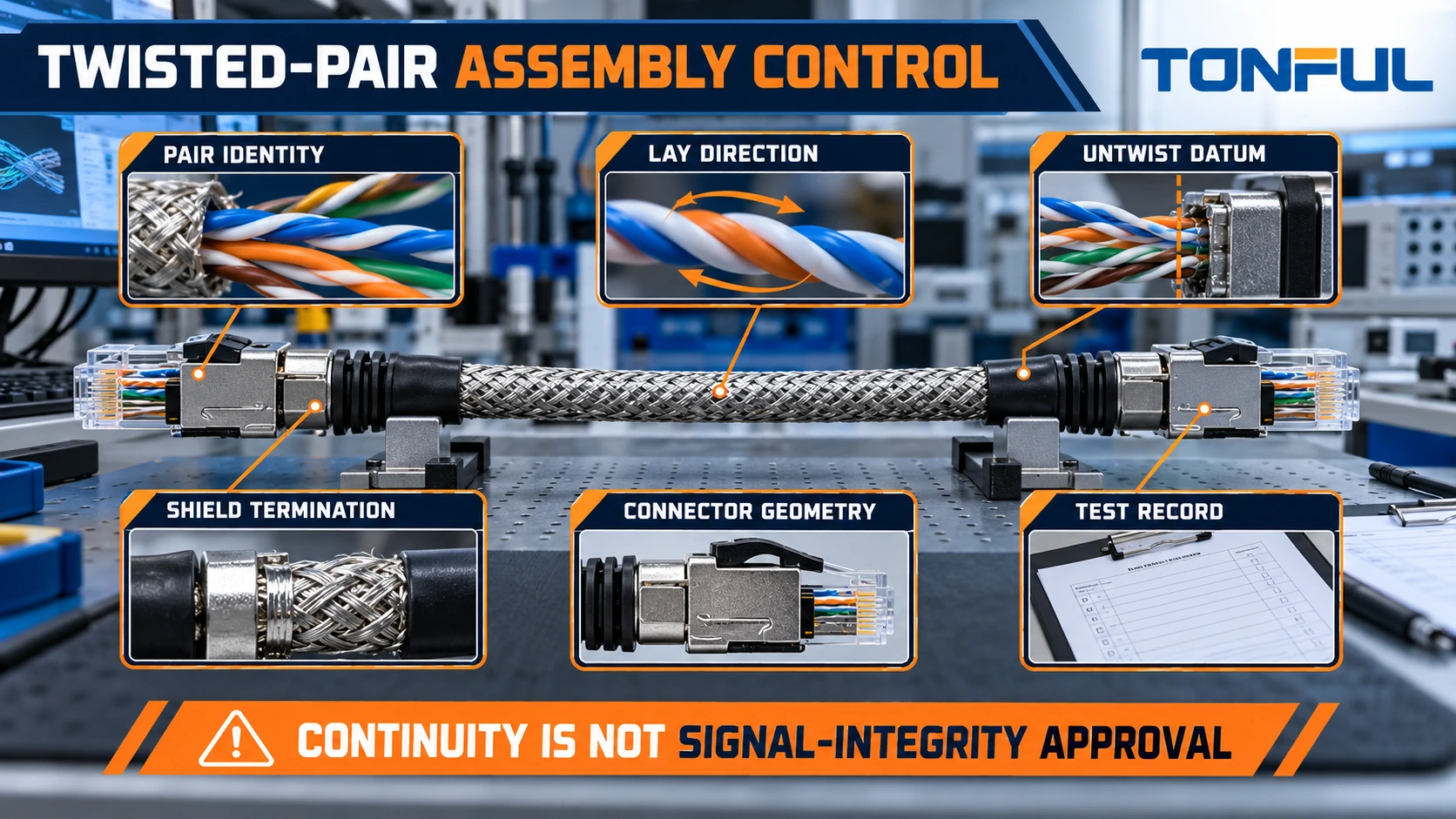
A twisted-pair cable assembly can pass a continuity test and still fail in service. Correct endpoints prove that conductors are connected, but they do not prove that the intended two wires remain a balanced pair, that twist is preserved near each termination, that characteristic impedance is controlled, or that shielding and connector geometry support the required signal.
These risks apply to many differential and balanced interfaces, including industrial Ethernet, CAN, RS-485 and product-specific high-speed links. The exact impedance, bandwidth, pair lay, maximum untwist and test limits are not universal. They must come from the cable specification, connector application documents, interface requirement and approved assembly test plan.
This guide explains how to preserve the cable’s electrical structure from incoming reel to finished assembly. It separates workmanship controls from performance evidence so buyers do not mistake a visually neat termination or a passing pin map for full signal-integrity approval.
Start With a Controlled Pair Map
The drawing must identify both members of every pair. Labels such as Pair 1 A/B, CAN_H/CAN_L or TX+/TX− should map to connector cavities at both ends. Do not specify only wire colors; similar colors, tracer variations and lighting conditions can create assembly errors. Record shield, drain and unused conductors separately.
For a multi-pair cable, define whether pairs may cross or change location inside a connector. A correct logical pinout can still create undesirable pair splitting if one conductor from Pair A is combined with one from Pair B. Production testers should verify each endpoint, but the work instruction must also show the physical pair grouping.
| Pair record field | Required entry |
|---|---|
| Pair ID | Unique pair name or circuit function |
| Positive/negative or A/B member | Controlled conductor identity |
| Cable color/tracer | Manufacturer’s exact identification |
| End A cavities | Connector and cavity references |
| End B cavities | Connector and cavity references |
| Shield/drain relation | Pair shield, overall shield or none |
| Polarity rule | Straight, crossed or product-specific mapping |
| Test requirement | Continuity plus applicable performance tests |
The TONFUL continuity-testing guide explains opens, shorts and miswire matrices. For twisted pairs, add a pair-integrity review because continuity alone cannot detect every split-pair condition when endpoints are incorrectly but consistently mapped.
Preserve Pair Geometry and Lay
Twisting helps a balanced circuit reject coupled interference because both conductors encounter a similar electromagnetic environment. Performance depends on the complete design: conductor diameter, insulation, spacing, lay length, shield, jacket and manufacturing consistency. Re-twisting two arbitrary wires by hand does not create a qualified data pair.
Specify the approved cable manufacturer, part number, pair count, conductor construction, nominal impedance where applicable, shield arrangement, jacket and relevant performance category. Preserve the cable’s original lay direction unless the cable or connector procedure requires otherwise. Do not reverse or add twist merely to make conductors reach a cavity.
TE Connectivity’s twisted-pair cable overview illustrates that specific products publish controlled impedance, pair constructions, flexibility and application performance. Those product values do not apply automatically to another cable; they demonstrate why the exact construction must be identified.
Avoid flattening, kinking or sharply bending the pair during cutting and routing. Ties and clamps should retain the assembly without crushing the geometry. If a pair exits an overall jacket, add support so branch motion is not transferred directly into the termination.
Control Jacket Strip-Back and Pair Untwist
Remove only the jacket length needed for the approved termination and strain-relief design. Excess strip-back exposes pairs to movement and changes the controlled cable geometry. Too little strip-back can prevent proper connector assembly or force a sharp bend.
Untwist only the distance needed to place conductors into the contact or lacing feature. The connector manufacturer’s instruction takes priority because different hardware controls conductors in different ways. Fluke Networks’ balanced-pair termination guidance emphasizes maintaining geometry close to the termination and following the connecting-hardware instructions. Its category-cabling example is not a universal untwist limit for CAN, custom differential cable or every connector.
Define where untwist is measured: from the last intact crossover, jacket edge, shield edge or another specified datum to the contact termination point. A statement such as “minimum untwist” is not auditable without a datum and limit. Record the measurement method, sample quantity and acceptance source.

Terminate Conductors Without Disturbing the Pair
The termination method may be crimp, insulation displacement, solder, weld or connector-specific process. Follow the approved application specification for conductor size, strip length, tooling, contact insertion and strain relief. Verify that the cable’s strand construction and insulation OD fit the contact and seal.
For crimped contacts, control strip quality, conductor brush, bellmouth, insulation support and crimp geometry as required. Pull testing evaluates mechanical attachment under defined conditions but does not establish signal performance. Cross-sections may confirm crimp formation; they also do not prove impedance continuity through the connector.
Maintain pair proximity while avoiding crossed strands, insulation damage or side loading. Where two contacts are inserted into separate cavities, the work instruction should show the routing path so operators do not untwist extra length for convenience. Use a fixture or marked preparation gauge when it improves repeatability.
Connector selection must consider the signal path, not only cavity count. The TONFUL industrial Ethernet M12 versus RJ45 guide explains how interface, environment and connector system affect the finished link. For custom interfaces, require product-specific electrical data rather than assuming any multi-pin connector preserves differential performance.
Control Shield and Drain Termination
Identify whether the design uses unshielded pairs, individually shielded pairs, an overall shield or a combination. Define the shield material, drain-wire relation, termination point, coverage treatment and chassis/circuit reference. Do not connect a drain wire to an arbitrary spare cavity.
The required termination may be a full circumferential connection, a pigtail, a dedicated contact or another controlled interface. These are not electrically interchangeable. A long pigtail can add inductance at high frequency, while an incorrect 360-degree clamp can damage the shield or jacket. Follow the connector, backshell and system grounding design.
At cable breakouts, prevent foil tearing, braid loss and shorting to signal contacts. Specify trim dimensions and insulation. The TONFUL EMI/RFI shielding guide compares foil and braid behavior, but final shield effectiveness depends on the complete cable, termination and enclosure path.

Separate DC Tests From Signal-Performance Tests
Use continuity/miswire testing to confirm endpoint mapping, shorts, opens, shield paths and prohibited connections. Record the approved pair matrix and fixture revision. If resistance is measured, define test current, compensation, test points and limits.
Signal-performance requirements depend on the interface and assembly. Possible measurements include characteristic impedance or time-domain reflectometry, insertion loss, return loss, crosstalk, delay, skew, common-mode conversion, eye diagram, bit-error performance or functional communication. Not every assembly needs every test. The approved plan should identify qualification, first-article and production coverage.
The TONFUL data-cable eye-diagram guide explains why DC continuity is only the first layer of high-speed verification. Do not claim a bandwidth, category or protocol based on cable type alone when connectors, termination and length can change the assembled result.
| Test layer | Primary question | Typical evidence | Does not prove |
|---|---|---|---|
| Visual/pair audit | Are pair identities and geometry preserved? | Photos, measurements, inspector record | Electrical performance |
| Continuity/miswire | Are endpoints and prohibited paths correct? | Automated matrix result | Impedance or crosstalk |
| Shield continuity | Is the intended shield path connected? | Defined resistance/path result | Shield effectiveness at frequency |
| TDR/impedance | Are discontinuities within the approved requirement? | Trace, limits and fixture reference | Full protocol operation |
| Frequency-domain test | Are loss/crosstalk requirements met? | Calibrated sweep and report | Environmental durability |
| Functional/eye/BER | Does the link operate under defined conditions? | Setup, pattern, duration and result | Every installation condition |
Control Fixtures, Calibration and Reference Planes
Performance measurements are only meaningful when reference planes and fixture effects are defined. Record instruments, software, calibration status, adapters, test cables, de-embedding or compensation, fixture revision and environmental condition. A golden sample can monitor drift, but it should not replace traceable calibration or a numerical requirement.
Define whether results include both connectors, flying leads, PCB transitions or adapters. Use the same boundary for baseline and aged measurements. If adapters dominate the result, improve the fixture or document the limitation before approving the product.
For production, establish a reaction plan for test failures. Quarantine the lot, preserve raw data, inspect pair identity and termination, verify fixture health and repeat only under an approved retest rule. Do not keep reconnecting until a marginal assembly passes.
Validate Mechanical and Environmental Effects
Electrical performance can change after flexing, vibration, thermal cycling, humidity, fluid exposure or connector mating. Select conditioning that reflects the actual application and governing requirement. Record sample quantity and allocation, preconditioning, sequence, monitoring, acceptance criteria and failure analysis.
Overmold and strain-relief processes require special attention. Heat, pressure or resin flow can move pairs, change conductor spacing or create a stiff transition that concentrates bending. TONFUL’s overmolded data-cable assembly guide explains why geometry and process windows must be validated rather than judged only by exterior appearance.
Compare initial and post-conditioning traces when the plan requires it. Preserve first-failure location and symptom. A discontinuity near a connector may indicate termination geometry, while a mid-span change may point to cable damage or fixture handling. Investigation should follow evidence rather than automatically blaming the cable.

Copyable Twisted-Pair Assembly Record
| Record field | Required entry |
|---|---|
| Assembly identity | Part number, revision, lot and sample ID |
| Cable identity | Manufacturer, part, lot, pair count and construction |
| Pair map | Pair/member IDs and connector cavities at both ends |
| Preparation | Jacket strip datum/length and untwist datum/result |
| Termination | Connector/contact, tool, process and inspection result |
| Shield path | Shield/drain construction and termination method |
| Fixture boundary | Adapters, reference planes and fixture revision |
| DC tests | Continuity, resistance and shield-path results |
| Signal tests | Method, frequency/data condition, raw result and limit |
| Conditioning | Sequence, sample allocation and post-test evidence |
| Acceptance source | Drawing/specification, revision and section |
| Disposition | Pass/fail, failure mode, reviewer and date |
Specify Twisted-Pair Assemblies With TONFUL
Send TONFUL the controlled cable and connector part numbers, pair map, pinout, strip and untwist requirements, shield termination, mechanical route, required performance tests, fixtures/reference planes and acceptance sources. TONFUL can review pair-level work instructions, termination controls, inspection records and production testability against the released design. Protocol, impedance and environmental claims remain tied to the approved component set and completed-assembly evidence.