
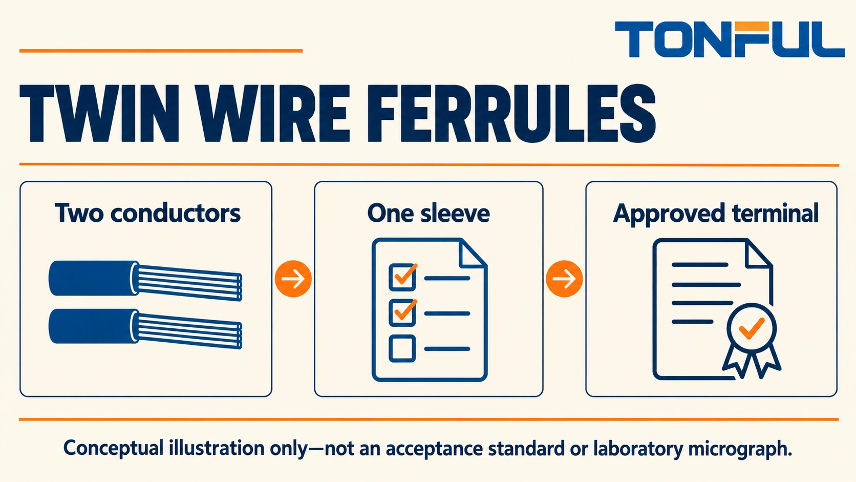
Twin wire ferrules prepare two stranded conductors for insertion into one approved terminal connection. Their shared metal sleeve contains the prepared strands, while a wider insulating collar guides the two wire entries. They are not simply oversized single-wire ferrules, and they do not make every terminal suitable for two conductors.
Selection requires two approvals: the ferrule must accept the exact conductor pair, and the receiving terminal must accept that ferruled configuration. Only then should tooling, strip length and production inspection be finalized. This guide turns those checks into a sizing worksheet and release record without inventing a universal wire-area conversion rule.
Jump to: Twin ferrule sizing | Terminal compatibility | Process setup | Verification plan | Service decisions | Purchase release
Twin ferrule sizing
Preserve the pair notation
A twin ferrule’s designation commonly identifies a pair of conductors, rather than the size of one larger conductor. Read the manufacturer’s notation and drawing together. For example, the official Phoenix Contact AI-TWIN product document identifies a twin-ferrule construction and dimensions for its specific product. It is a useful example of the documentation needed, not approval of another manufacturer’s ferrule.
Write the conductor pair explicitly in the bill of materials. Do not replace that description with a single summed area or a familiar collar color. Color conventions vary, and the same nominal area can be supplied with different strand construction and insulation dimensions. Purchasing by color alone can introduce a different sleeve or an unsuitable wire-entry opening.
Area is not the complete fit calculation
Two equal-area conductors do not necessarily pack into a sleeve like one conductor with their combined area. Strand arrangement, strand diameter, sleeve shape, wall thickness and final crimp profile all affect the envelope. The insulating collar must also accept both jackets without shaving, buckling or preventing full strand insertion.
The NASA equivalent-wire-size multiplier used for certain butt-splice applications is not a twin-ferrule sizing rule. Do not apply a butt-splice calculation to select ferrules. Use the ferrule manufacturer’s approved conductor-pair combinations and the receiving terminal manufacturer’s connection data, with engineering approval of any configuration not explicitly covered.
| Worksheet item | Required entry | What it prevents |
|---|---|---|
| Conductor A | Part number, material, area and strand class | Selecting by gauge alone |
| Conductor B | Same fields, recorded independently | Assuming both wires are identical |
| Jacket fit | Outside diameter of each wire | Collar interference |
| Ferrule | Exact twin designation and drawing revision | Substituting a single-wire sleeve |
| Sleeve | Metal length and approved prepared-wire length | Incomplete clamp engagement |
| Crimp | Tool, cavity and final profile | An incompatible finished envelope |
For unequal conductor sizes, request explicit confirmation of the combination. A sleeve that accepts the larger wire physically may not retain the smaller wire adequately. Do not fold a conductor, add strands or substitute a larger sleeve to make an unapproved pair appear to fit.

Terminal compatibility
Read connection data for the exact terminal
Check the receiving terminal’s conductor information for ferruled conductors and twin ferrules specifically. A bare-stranded range, a single-ferrule range and a twin-ferrule range can differ. A terminal’s general maximum conductor size does not establish permission for a two-wire ferrule, even when the sleeve can enter the opening.
Confirm the permitted sleeve length and crimp shape. A square, trapezoidal or hexagonal finished sleeve may present a different width or diagonal to a narrow entry. Avoid forcing the ferrule through the opening, trimming its metal end or reshaping it with pliers. Mechanical entry without correct clamping engagement is not a completed compatibility review.
Check the whole insertion path
The plastic collar must remain clear of the conducting clamp region. Too short a sleeve can leave part of the intended contact region unsupported; an excessively long sleeve can create exposed metal or bottom out before proper seating. Use the terminal instruction to establish insertion depth and the permitted relationship between collar, housing and metal contact.
Include neighboring poles, screwdriver access, wire bend direction and identification sleeves in the layout review. Twin wires can require more routing space than a single wire, particularly near a door hinge or cable duct. TONFUL’s cord end terminal range provides a starting point for ferrule discussions, but the mating equipment still determines what it accepts.
| Compatibility question | Evidence | Release condition |
|---|---|---|
| Is the pair allowed? | Terminal connection data | Exact configuration covered or approved |
| Does the sleeve engage correctly? | Sleeve and terminal drawings | Length and contact zone match |
| Does the profile fit? | Tool profile and entry geometry | Normal insertion without reworking |
| Can the collar clear the housing? | Physical layout review | No blocked insertion or clamp contact |
| Can both wires route safely? | Assembly drawing | Bend and support provisions defined |
Process setup
Control preparation before crimping
Isolate and verify the safe state before working on wiring. Establish strip length from the ferrule and terminal instructions, not a generic rule. Prepare both ends so that the intended bare conductor length enters the sleeve and insulation is not trapped inside the metal crimp zone. Examine strands for cuts, missing filaments or severe distortion.
Keep the two conductors together without adding solder or trimming strands to reduce diameter. Tinning strands changes the termination system and should not be introduced as an operator workaround. If the pair cannot be inserted consistently using the approved preparation method, resolve the combination or preparation process rather than relying on individual operator technique.
Match the tool to the twin ferrule
Use a tool and cavity approved for the selected twin ferrule and wire combination. A tool’s advertised single-wire range is not automatically its twin-wire range. Check the ferrule support, insertion orientation and operating sequence. Confirm the finished profile fits the receiving terminal before releasing production quantities.
Discuss the exact sleeve and conductor pair when reviewing TONFUL’s crimping tools. The relevant evidence is a compatible tool/ferrule system, not the presence of a ratchet alone. Record the tool identifier and applicable setup in the work instruction so that shifts cannot substitute a visually similar cavity without authorization.
Inspect for incomplete insertion, loose strands, a split sleeve, damaged collar or severe distortion. The two conductors should reach the required position independently; a common collar can hide a shorter conductor that never entered the full crimp region. Use first-piece samples to establish how the station verifies both wire ends before crimping.
Verification plan
Separate ferrule retention from terminal clamping
The crimp holds the prepared conductors within the sleeve, while the receiving terminal establishes the installed electrical and mechanical connection. Testing one does not prove the other. Plan evaluations that represent both the prepared twin ferrule and its installation in the intended terminal, where required by the approved specification.
If mechanical tests are required, define whether each conductor is loaded individually or the pair is loaded together, plus grip locations, fixture alignment, speed and acceptance source. A combined pull can conceal weak retention of one wire. Do not choose a universal force threshold from an unrelated terminal or single-wire ferrule table.
For electrical checks, define the measured boundary, current, instrumentation range and accuracy, ambient condition and connection procedure. A continuity buzzer only confirms a path at its own operating conditions. Qualification may also need thermal or environmental evidence, but the applicable equipment and risk assessment determine that scope.

Use a reproducible record
| Record field | Information to preserve |
|---|---|
| Sample definition | Wire A/B lots, ferrule lot and terminal identity |
| Preparation | Strip instruction, tool, cavity and profile |
| Installation | Insertion evidence and terminal operating instruction |
| Sampling | Approved quantity, configuration coverage and rationale |
| Test method | Fixture, loading or electrical method, conditions |
| Acceptance | Document number, revision and exact criterion |
| Outcome | Individual results, defects and disposition |
| Exceptions | Invalid-test cause, retest authorization and retained evidence |
Do not report an invalid fixture failure as a passing product result after quietly discarding it. Keep the original observation, explain why it was invalid and apply the preapproved retest rule. When a valid sample fails, contain the affected configuration and investigate before expanding the sampling plan.
Service decisions
Evaluate a terminal substitution separately
Suppose a panel revision replaces the receiving terminal while retaining the approved twin ferrule and both wires. This hypothetical change still needs a compatibility review. Compare the new terminal’s twin-ferrule connection data, insertion depth and entry envelope with the existing finished crimp. Preserve the original approval record rather than overwriting its terminal identity.
Where the new terminal accepts the combination, perform the required installation verification using production-prepared samples and the correct operating instruction. Where it does not, choose a different approved ferrule/terminal arrangement or separate connection positions. Do not machine the collar, shorten the sleeve or compress the profile a second time to preserve the old bill of materials. Record the selected configuration and withdraw superseded station instructions before releasing the revised panel.
Consider whether two wires should share a connection
A twin ferrule can be useful for an approved loop-through connection, but it couples service actions. Removing one shared termination disconnects both wires. Where independent isolation or replacement is important, separate terminal positions and an approved distribution method can be easier to maintain and inspect.
Do not assume a ferrule acts as a free-standing splice. Its intended use is preparation for a compatible terminal connection. For wire-to-wire joining or stud mounting, evaluate the appropriate architecture instead. TONFUL’s non-insulated terminal category and nylon-insulated terminal category cover different connection functions; those parts are not substitutes for ferrules merely because both receive a crimp.
Plan repair length and access before installation. Cutting off a twin ferrule shortens both wires and may make reinsertion impossible without rerouting. Avoid opening and reusing a previously crimped sleeve unless a specifically approved method permits it. Use a fresh ferrule and prepared ends under the equipment’s authorized service procedure.
Purchase release
Freeze the combination rather than the color
The purchase specification should identify the twin ferrule, approved conductor pair, metal sleeve length, collar dimensions, tooling and receiving-terminal configuration. Require supplier notification of changes that affect those characteristics. If alternate sources are allowed, qualify the alternate combination rather than accepting an unchanged nominal designation as equivalent.
For incoming material, compare the delivery identification with the approved drawing and sample record. Keep ferrules separated by part number and lot. A mixed tray of similar collar colors can defeat an otherwise well-controlled crimp process, especially where two sleeve lengths share the same conductor designation.
Send TONFUL your two wire specifications, terminal manufacturer and part number, available entry space and intended tooling. Request part-specific drawings and samples through the wire terminal sourcing page, then approve the ferrule and receiving terminal as a combination. That process produces a defensible sizing decision without turning a nominal wire-area sum into an unsupported compatibility claim.