
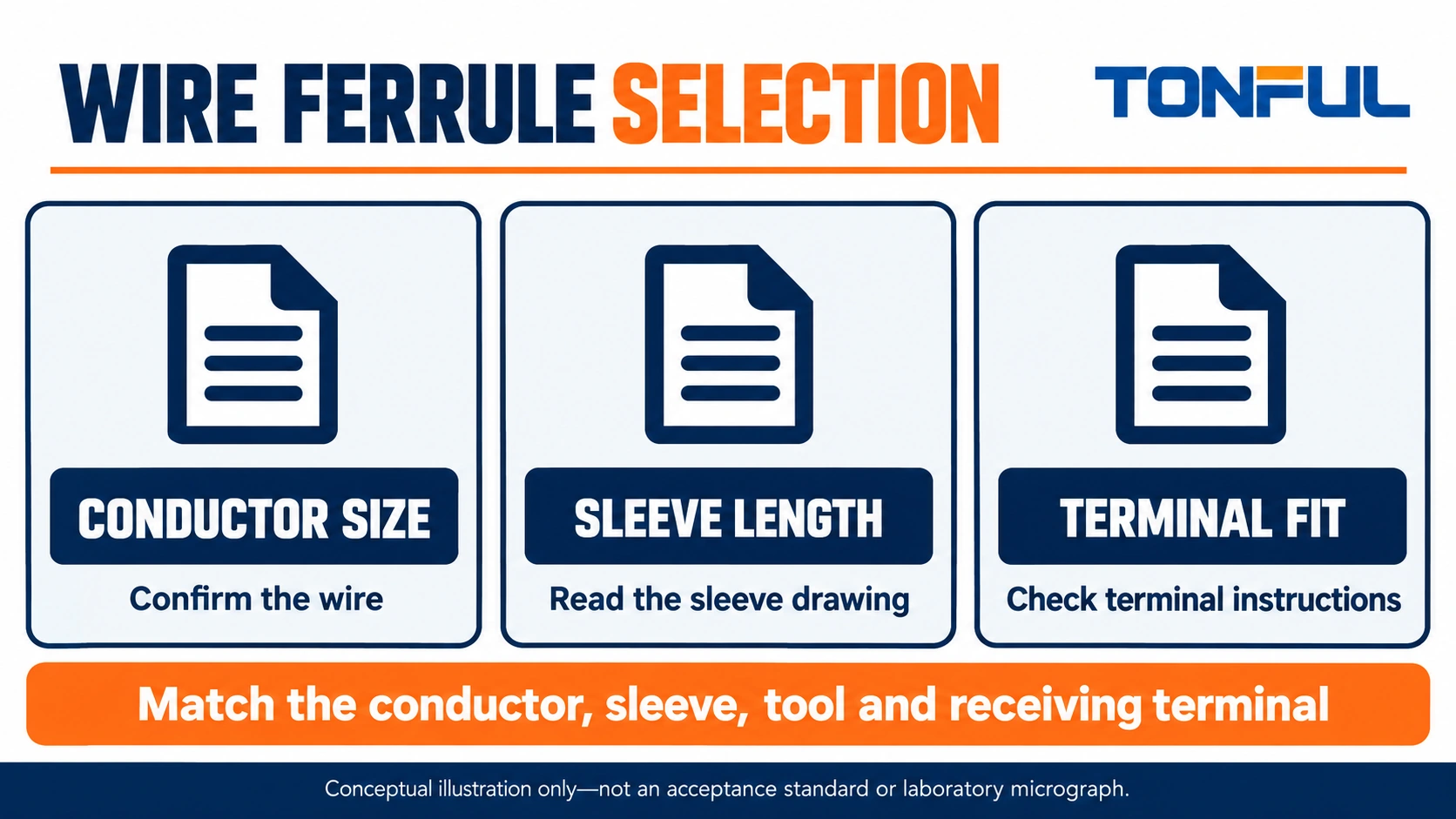
Wire ferrule selection is a compatibility check between the conductor, the ferrule, the forming tool and the receiving terminal. Matching nominal conductor size is necessary, but it does not settle sleeve length or whether the finished crimp fits the clamping space. A ferrule that enters an opening can still be unsuitable for the actual terminal instruction.
Start with the receiving terminal’s permitted conductor preparation, then select the ferrule and tooling around the real wire. This guide provides a decision table and release record for that process. It does not assume that every stranded conductor needs a ferrule or that a plastic collar makes the finished connection fully insulated.
Jump to: Permission | Conductor | Length | Crimp profile | Record | Sourcing
Wire Ferrule Selection Starts at the Receiving Terminal
Read the permitted conductor information
Identify the receiving terminal by manufacturer, part number and instruction revision. Check its permitted conductor types, conductor ranges and preparation methods. A range listed for a bare flexible conductor may differ from the range listed for a ferruled conductor. Do not carry one value into the other category without confirmation.
Some terminal systems accept appropriately prepared stranded conductors without ferrules; others provide specific ferrule guidance. Follow the actual system information rather than treating ferrules as an automatic upgrade. The selection question is whether the specified conductor preparation is accepted and suitable for that terminal and application.
For primary-source context, Phoenix Contact’s ferrule guidance discusses the relationship among sleeve length, stripping and crimp profile. Its guidance and product approvals are not evidence that another supplier’s ferrule is universally interchangeable. Use the receiving-terminal and selected-ferrule instructions for the actual release.
Define the physical interfaces
The conductor enters the ferrule tube, the tool forms that tube around the conductor, and the finished end enters the receiving terminal. The collar, when present, guides entry and occupies space outside the metal sleeve. Each interface needs its own check. Do not describe a ferrule as a solid pin terminal or use a pin-terminal drawing to approve its geometry.
TONFUL’s cord-end terminal range provides a starting point for single, twin and bare ferrule candidates. Confirm exact dimensions and application information for the selected part. Catalog family descriptions establish the type of product offered, not blanket compatibility with every screw, spring or push-in terminal.
Match the Ferrule to the Conductor
Specify actual wire construction
Record conductor material, nominal cross-section, strand construction and wire part number. Use the wire document rather than inferring area from insulation thickness or color. Where AWG and metric descriptions appear together, preserve the manufacturer’s stated compatibility rather than treating approximate conversions as exact dimensional equivalence.
A nominal ferrule size is not a license to alter the wire. Do not cut strands to insert a conductor, fold a small conductor back to fill a tube or substitute another strand construction without review. If insertion is difficult, check preparation, size and permitted construction before changing the assembly method.
Include insulation outside diameter
The tube receives the conductor, while a collar must accommodate the incoming jacket. A conductor can match the nominal ferrule size and still have a jacket that does not enter the collar as intended. Obtain the relevant entry geometry and confirm the wire outside diameter. Do not force the collar over an unsuitable jacket or remove extra insulation to bypass it.
Color can help operators pick parts after the product coding system is identified, but it is not a universal cross-section reference across all ferrule systems. Keep part number and nominal size visible on labels and work instructions. When stock is transferred to bins, retain traceability instead of replacing the supplier identification with a color-only description.
Keep single and twin selections distinct
A twin ferrule is intended for specified two-wire arrangements, not any two conductors whose nominal areas can be added. Confirm the permitted combination, collar entry, tube capacity and receiving-terminal range. Do not place two wires into a single-wire ferrule unless that exact arrangement is approved by the applicable documentation.
For this selection guide, treat twin ferrules as a separate part and qualification decision rather than expanding the single-wire table with guessed combinations. Also confirm that the receiving terminal accepts the resulting prepared end. Combining wires can change routing, collar width and the space required outside the clamp even if insertion appears possible.
Select Sleeve Length and Collar Clearance
Distinguish metal sleeve length from overall length
The metal sleeve is the region presented to the receiving terminal; overall length may also include the collar. Specify both when they affect the assembly. Do not order by overall length alone and assume it describes how far the prepared conductor extends into the clamping region. Obtain a drawing with the dimensions clearly identified.
Choose sleeve length against the receiving-terminal instruction and the ferrule’s application information. A sleeve that is too short for the required preparation can leave the clamping arrangement engaging an unintended region. An unsuitable long sleeve can bottom out or leave exposed conductive material. Do not establish a universal length rule from one terminal family’s example.
| Length or clearance check | Document needed | Selection question |
|---|---|---|
| Metal sleeve length | Ferrule drawing | Is the intended clamping region covered as required? |
| Required insertion/preparation | Receiving-terminal instruction | Can the prepared end reach the intended position? |
| Collar length and width | Ferrule drawing | Does the collar clear the terminal entry and neighbors? |
| Strip length | Approved ferrule application instruction | Can the conductor occupy the sleeve as specified? |
| Exposed metal after installation | Assembly review | Is guarding and spacing addressed? |
| Wire exit envelope | Installed drawing | Can the jacket and routing remain unstressed? |
Do not use the collar as a seating stop by assumption
Confirm how the terminal instruction defines full insertion. A collar touching the outside of an equipment terminal does not necessarily prove that the metal sleeve is correctly positioned inside. Conversely, a gap outside the entry may be acceptable or unacceptable depending on the specified arrangement. Use the documented criterion, not a general appearance rule.
Check neighboring poles and the enclosure cover with the actual collar shape. Twin collars or long-entry collars can interfere where a single ferrule fits. If a bare ferrule is selected for space or another documented reason, review its conductor preparation and assembly protection separately rather than assuming that removing the collar preserves all other dimensions.

Review the Finished Crimp Profile
Select tooling for the ferrule system
Identify the approved tool, working range and forming profile for the candidate ferrule and wire. Square, hexagonal and other profiles should not be ranked as universal winners. Their suitability depends on the ferrule application and receiving-terminal geometry. The relevant question is whether the approved finished profile fits and functions in the intended clamping space.
Use TONFUL’s crimping-tool information to request a matched tooling recommendation. A self-adjusting mechanism is not proof of compatibility with every sleeve, and a nominal size range alone does not specify the full process. Record tool identity and any required setup or inspection information before evaluating samples.
Do not force an unsuitable prepared end
Review the finished profile and dimensions against the terminal entry and clamping instructions. If it does not enter as intended, do not flatten, trim or reshape it with unrelated tools. Investigate the ferrule, conductor, tool and receiving-terminal combination. An improvised shape change hides the mismatch without creating an approved process.
Keep stripping and forming operations consistent during trial fit. A sample made from a different wire construction or an unidentified tool cannot demonstrate the intended production combination. Record the actual setup so the fit review can be repeated and so purchasing can recognize which substitutions require renewed approval.
For a panel containing several receiving-terminal families, create a cross-reference rather than assuming one ferrule covers the entire wire size. Give each receiving part its own permitted preparation, sleeve-length choice and tooling reference. Common inventory may be possible after review, but a successful fit in one clamp cannot approve the others. This distinction is especially useful when purchasing wants to reduce ferrule variants without changing the released panel design.
Create a Ferrule Compatibility Record
Connect four identities to one release
Use the following editorial template to record the wire, ferrule, tool and receiving terminal. Enter actual document references and reviewers; the table is not a report of completed qualification. An unanswered row is a hold point, especially when a supplier proposes a visually similar ferrule with another collar or sleeve length.
| Record field | Required entry | Hold condition |
|---|---|---|
| Wire | Part, size, material, strands and jacket diameter | Construction not confirmed |
| Ferrule | Part, sleeve length, collar and drawing revision | Only color or nominal size known |
| Tool | Model, range, profile and instruction | Unidentified forming method |
| Receiving terminal | Part and ferruled-conductor permissions | Ferrule use/range unclear |
| Installed fit | Insertion, collar, cover and routing review | Interference or seating uncertainty |
| Verification | Applicable methods and acceptance source | Borrowed universal limits |
| Approval | Responsible owner, revision and date | Open substitution or deviation |

Verify under the applicable plan
Inspect prepared samples against the actual application instruction, including strand containment, sleeve condition and insertion. Where the design requires mechanical, electrical or environmental verification, define the method and acceptance source in the qualification plan. Do not copy a ring-terminal pull-force limit or another supplier’s crimp dimension into a ferrule release record.
Install and inspect only on safely isolated equipment, with stored energy controlled and the deenergized state verified by qualified personnel. A plastic collar does not make the receiving clamp safe to touch while energized. For equipment with specialized safety requirements, use its approved termination and service process rather than treating this selection guide as authorization for substitution.
Send TONFUL the Complete Selection Brief
Include the wire document, receiving-terminal part number, permitted preparation range, desired sleeve length and installed-space constraints. Add the intended tool or request a tooling recommendation. State whether the inquiry concerns a new panel design, a production substitution or a controlled service replacement, because the evidence needed for release may differ.
Use TONFUL’s wire-terminal sourcing team to review candidate ferrules with their drawings and application information. Keep a clear distinction between ferrules and other bare terminal constructions when describing the need. If the destination instead needs a stud tongue or blade interface, return to that terminal family rather than trying to use a ferrule as an adapter.
For buyers comparing collar constructions, the existing insulated versus non-insulated ferrule discussion is a supporting resource. The final release should still name the actual wire, sleeve, tool and receiving terminal. Ask TONFUL for the part-specific evidence needed to close those four interfaces before approving production supply.