
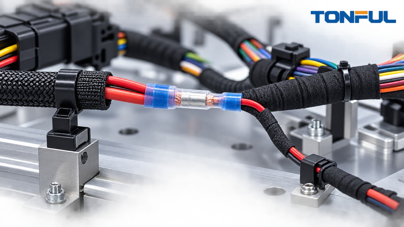

Automotive wiring harnesses often transition from a larger feed wire to a smaller branch, lamp lead, motor pigtail, sensor supply, or accessory circuit. A step-down butt connector can make that transition with one splice body and two differently sized crimp zones. It is useful only when the circuit design permits the smaller wire, the vehicle or equipment specification permits a crimped splice, and the complete wire-connector-tool combination is validated for its location.
A reducing splice does not determine wire ampacity, fuse size, voltage drop, temperature class, or functional safety. Those decisions belong to the circuit and harness design. The connector’s job is to create a controlled mechanical and electrical transition between two approved conductors.
Where Step-Down Splices Are Useful
Common design situations include:
- A larger power feed transitioning to a lower-current branch
- A replacement pigtail with a different wire gauge
- An accessory harness joining an established vehicle circuit
- A controlled service repair outside a connector cavity
- A prototype or low-volume harness with unequal wire sizes
- An OEM subassembly whose device lead is smaller than the main harness conductor
- A controlled breakout where one branch has a lower design current than the trunk
Before selecting a splice, verify that the circuit drawing intentionally uses both wire sizes. The connector must not be used to justify an undersized downstream wire or to bypass a conductor-sizing review. Circuit protection, steady-state and transient current, voltage drop, bundling, ambient temperature, duty cycle, fault behavior, and derating remain engineering inputs.
TONFUL’s custom automotive wire harness guide discusses heat and packaging constraints.
Where a Step-Down Splice Should Not Be Assumed
Do not treat a catalog connector as automatic approval for:
- Airbag, restraint, braking, steering, or other safety-related circuits
- High-voltage EV wiring or orange high-voltage cable systems
- Data buses, shielded cable, coaxial cable, or controlled-impedance circuits
- Aluminum-to-copper transitions unless the connector is specifically approved for both metals
- Locations where the OEM repair manual prohibits splicing
- Moving hinge areas, repeated-flex zones, or unsupported breakouts
- Connector-cavity repairs that require a replacement terminal and seal rather than an inline splice
Use the vehicle, harness, device, and customer specifications as the controlling authority.
Validate the Complete Wire Pair

Specify both wires completely. Thin-wall automotive wire can have a different insulation diameter and strand behavior from general-purpose stranded wire of the same AWG. A connector can appear to fit the jacket while the conductor is outside the barrel’s qualified range.
| Design input | Large-wire side | Small-wire side | Why it matters |
|---|---|---|---|
| Wire part number and governing specification | Record | Record | Prevents substitution by nominal AWG alone |
| Conductor size, material, and plating | Record | Record | Determines conductor fit and electrical interface |
| Strand count and construction | Record | Record | Affects insertion, compaction, and pull behavior |
| Insulation material and outside diameter | Record | Record | Affects sleeve fit, sealing, and strain support |
| Temperature class | Record | Record | Must suit the harness location and load condition |
| Strip length and allowable strand damage | Record | Record | Controls conductor position and effective area |
| Circuit current and protection | Engineering input | Engineering input | Confirms the wire transition belongs in the design |
For multi-wire insertion into either end, use the applicable approved sizing method and the connector manufacturer’s documentation. Do not simply add insulation diameters or force a conductor bundle into a nominal range.
Use TONFUL’s wire AWG and insulation selection guide to organize these inputs.
Tooling Is a Two-End Process
The large and small barrels may require separate dies, cavities, applicator settings, or crimp-height windows. A color-coded hand-tool cavity is not approval by itself. The work instruction should identify:
- Tool and die part number
- Cavity for each end
- Connector orientation
- Strip length and insertion method
- Crimp height or other process controls
- Inspection and test frequency
- Crimp-height limits or other controlled dimensions for each end
- Tool verification, calibration, and maintenance requirements
- Seal or heat-shrink process parameters where applicable
- Reaction plan for out-of-limit results
An approved ratchet tool may suit prototype or authorized service work, while controlled presses and applicators may suit volume production. Production planning should count two crimp terminations per splice and control each end as a separate interface.
First-piece approval should confirm wire preparation, insertion, connector orientation, crimp location, measured result, and visual condition on both ends. If either wire, terminal lot, die, tool setting, or material changes, evaluate whether revalidation is required.
Vibration, Flexing, and Routing
Place the splice in a supported straight section, not at a hinge, sharp bend, breakout flex point, or location where the harness pulls on the conductor exit. Keep rigid splice bodies away from repeated-flex zones and provide enough straight wire for tool access, sealing, strain transition, and inspection.
Check the installed package against clips, conduit, grommets, brackets, sheet-metal edges, hot surfaces, moving components, and adjacent connectors. A splice that passes a bench pull test can still fail in service if routing concentrates bending or abrasion at the barrel exit.
TONFUL’s guide to wire harness protection methods compares sleeves, tubing, tape, and conduit options.
Sealing and Temperature

Cabin, engine-bay, underbody, wheel-area, door, and exterior-lighting environments impose different heat, fluid, splash, salt, abrasion, and movement conditions. Choose insulation and sealing based on the actual zone rather than the word “automotive.”
| Harness location | Typical design concerns | Connector and process questions |
|---|---|---|
| Dry cabin or protected enclosure | Packaging, service access, vibration | Is an insulated or separately protected splice permitted? |
| Engine bay | Heat, fluids, vibration, nearby hot surfaces | Are sleeve, adhesive, wire jacket, and barrel validated for the specified exposures? |
| Underbody or exterior | Splash, salt, abrasion, stone impact | Is the complete sealed splice and harness covering qualified for the location? |
| Door, tailgate, or hinge route | Repeated flexing and limited space | Can the splice be relocated outside the dynamic bend zone? |
| Device pigtail | Mixed wire sizes and short available leads | Is there enough conductor length for insertion, strain relief, and future service? |
Adhesive-lined heat shrink can add environmental protection and distribute strain, but it must be compatible with both wire jackets and installed with a controlled heating process. Define heating equipment, temperature control or approved method, heating direction, recovery condition, adhesive-flow criteria, cooling, and inspection. Do not use an open flame unless the approved process explicitly permits it.
Review TONFUL’s high-temperature automotive heat-shrink tubing guide when heat exposure is relevant.
Testing and Acceptance
The official IPC automotive and e-mobility resources identify IPC/WHMA-A-620 among standards used for cable and harness assemblies. Customer drawings, OEM specifications, component application specifications, and approved control plans may impose additional or different requirements. State the applicable document and revision instead of claiming general “automotive compliance.”
A practical validation plan separates the small and large crimp interfaces and then evaluates the complete splice. Do not insert universal acceptance numbers; fill every limit from the controlling product or customer document.
| Validation item | Small end | Large end | Complete automotive splice |
|---|---|---|---|
| Wire preparation and insertion | Inspect to controlled criteria | Inspect to controlled criteria | Confirm orientation and insulation gaps |
| Crimp height or controlled dimension | Measure when specified; use small-end limit | Measure when specified; use large-end limit | Not normally one shared value |
| Pull force | Test when specified using the small wire’s source requirement | Test when specified using the large wire’s source requirement | Assembly pull only when required |
| Electrical resistance | Included in the defined measurement path | Included in the defined measurement path | Record initial value and change after conditioning when specified |
| Cross-section | Required when specified by qualification or investigation | Required when specified by qualification or investigation | Section locations must be defined |
| Thermal cycling and vibration | Evaluate interface as specified | Evaluate interface as specified | Required when specified by the qualification plan or customer |
| Fluid, humidity, salt, or splash exposure | Evaluate materials as specified | Evaluate materials as specified | Required for applicable locations and specifications |
| Harness-level inspection | Not applicable alone | Not applicable alone | Verify continuity, routing, strain relief, covering, labels, and dimensions |
TONFUL’s IPC/WHMA-A-620 guide provides a buyer-oriented overview.
Production Control and Traceability
The production file should connect each finished splice to:
- Connector part number, revision, and lot
- Large- and small-side wire part numbers and lots
- Tool, die, cavity, applicator, and setting
- Approved work instruction and revision
- Operator and inspection authorization
- First-piece and periodic measurement records
- Pull-test or resistance records where required
- Heat-shrink or sealing process verification
- Nonconformance, rework, and concession records
Tool monitoring can detect incomplete cycles or setup changes, but it does not replace wire verification, visual inspection, dimensional measurement, or the validation plan.
Design Review Checklist
Before release, confirm:
- The circuit drawing intentionally permits the wire-size transition.
- The smaller conductor is protected for its current, temperature, bundling, and fault conditions.
- Both exact wire constructions fit the documented connector ranges.
- Each end has an approved tool, cavity, setting, and acceptance source.
- The splice location avoids prohibited, high-flex, hot, or abrasion-prone zones.
- Environmental protection is specified for the actual vehicle location.
- Validation covers both unequal crimp interfaces and the finished splice.
- Production and service documentation identify allowable parts and methods.
- Traceability and change-control requirements are defined.
- Vehicle, OEM, and customer restrictions have been reviewed.
Service Repair vs. Production Design
A repair connector should follow the vehicle or equipment manufacturer’s service procedure. Some circuits, locations, safety functions, or warranty programs prohibit splicing or require a named repair kit, wire, crimp tool, seal, or replacement sub-harness.
Do not reuse a crimped connector. A repair normally consumes wire length when the old splice is removed, so verify that both conductors can still reach the approved splice location without tension. Do not extend a safety-related circuit with a generic jumper unless the controlling repair instruction permits it.
Never present a universal TONFUL connector as automatic approval for airbags, high-voltage systems, braking, steering, restraints, or other safety-critical wiring.
Questions Buyers Should Ask the Supplier
- Which exact wire constructions have been validated on both ends?
- What connector drawing and revision control the part?
- Which tool, die, cavity, and process window apply to each end?
- Which dimensional, pull, resistance, and environmental reports are available?
- Which material, plating, insulation, adhesive, and packaging lots are traceable?
- Which changes trigger customer notification or requalification?
- Can the supplier provide crimped samples using the buyer’s actual wires?
- Are any automotive qualification or certification claims current and model-specific?
Source a Verified Automotive Splice
Share the two wire datasheets, circuit function, current and protection, vehicle location, temperature, fluids, vibration, sealing, routing envelope, available tooling, governing documents, test plan, packaging, and annual volume with TONFUL. Request a controlled drawing, tooling recommendation, crimped samples, and documented two-end validation plan before production release.
TONFUL can support feasibility and sample review, but final approval must remain with the vehicle, harness, or project authority responsible for the design.