
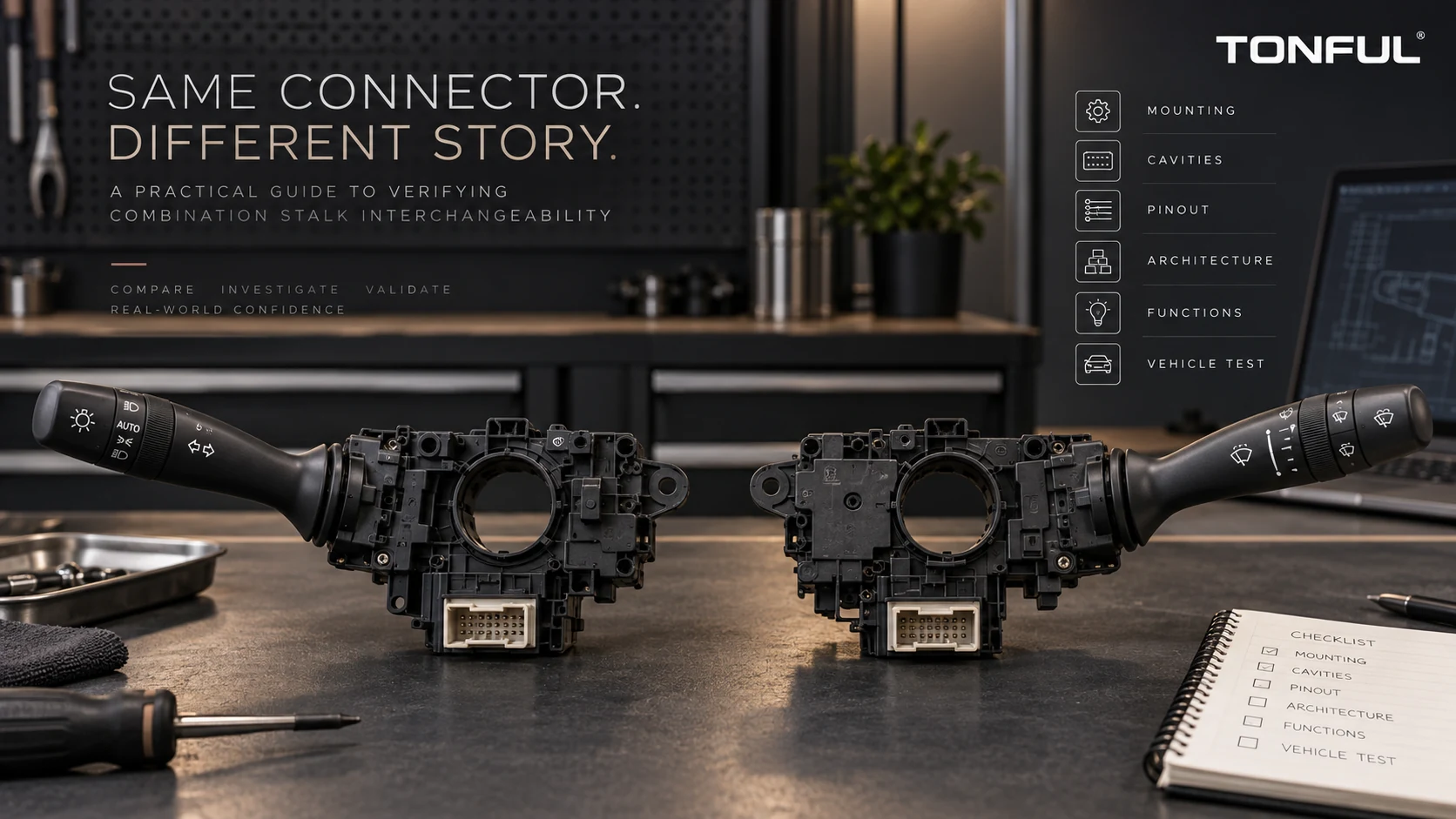
No. A matching connector shell is only one compatibility condition. Two combination switches can plug into the same harness yet assign different functions to the cavities, use different terminal populations, switch different loads, encode stalk positions with different resistance values, communicate with different module software or support different vehicle options.
Interchangeability should be released only after physical, electrical, functional and vehicle evidence agree. A connector that mates without force can still create no operation, reversed functions, blown protection, overheated contacts, network faults or an unavailable safety-related control.
On this page: Check Identity and Fit | Verify Electrical Architecture | Compare Every Function | Release the Application
Check Identity and Fit
Establish Vehicle and OE Scope
Capture vehicle make/model, market, production date or VIN/chassis boundary, trim, steering side, cab/body and option equipment. Record complete OE service number, suffix, supersession direction, supplier number and candidate number. Do not treat a molded housing number as the full switch number.
NHTSA’s vPIC can support manufacturer-reported VIN and basic vehicle identification for applicable U.S.-market vehicles. It does not confirm stalk-switch OE numbers, supersession, connector pinout, architecture, functions or interchangeability.
The combination switch OE cross-reference guide provides evidence-status fields. If the source or replacement direction is unverified, mark the candidate conditional or unverified rather than presenting it as a cross-reference.
Compare Physical Interfaces
Check mounting points, column diameter/interface, clock-spring clearance, trim envelope, stalk length/angle, self-cancel interface, LHD/RHD configuration and connector position. Compare shell part number, keying, latch, depth, CPA/TPA and mating force against controlled drawings.
| Physical field | Removed part | Candidate | Evidence | Result |
|---|---|---|---|---|
| Housing/mounting | Enter | Enter | Drawing/dimensions | Pass/Fail |
| Stalk side/angle | Enter | Enter | Vehicle/sample | Pass/Fail |
| Cancel interface | Enter | Enter | Mechanism drawing | Pass/Fail |
| Connector shell/key | Enter | Enter | End-view/drawing | Pass/Fail |
| Latch/lock/depth | Enter | Enter | Mating inspection | Pass/Fail |
| Column/trim clearance | Enter | Enter | Installed check | Pass/Fail |
The LHD versus RHD stalk guide explains why steering configuration, column side and function package must be verified independently.
Verify Electrical Architecture
Compare Cavity Population and Pinout
Fix viewing direction: switch header, mating face or wire-entry side. Record latch reference and every cavity, including blanks. Compare terminal size, gender, plating, seals and populated positions. The connector and harness interface checklist provides a complete record.
Then map supplies, grounds, illumination, direct loads, relay requests, resistor references and communication lines. A common shell may be used across multiple variants. One candidate can populate a formerly empty cavity or leave out a required terminal.
Never probe by applying battery voltage to unknown pins. Use vehicle diagrams, product drawings and protected test fixtures. A mirrored cavity map is not a minor documentation issue; it can damage an electronic input.
Identify Direct, Relay, Coded or Network Control
| Architecture | Compatibility evidence | Risk if assumed |
|---|---|---|
| Direct-load contacts | Contact map, load/current path, voltage drop, thermal and endurance evidence | Overheating, wrong output or arcing |
| Relay control | Coil/request polarity, load and downstream relay logic | No operation or unintended relay |
| Resistance/voltage coded | Reference/return, state windows, tolerance and module thresholds | Wrong decoded function |
| LIN/CAN/module | Supply, wake, protocol, message set, software/configuration | DTCs, no communication or wrong command |
The analog, resistive, LIN and CAN stalk guide explains these interfaces. Same connector plus same nominal voltage does not prove the same architecture.
For a 12 V or 24 V vehicle, identify each power domain. Illumination, logic reference, transceiver and direct load may not share one voltage. The switch’s contact or electronic protection requirements must be verified from product-specific documents.

A shared connector family can support different terminals, cavity assignments, load paths and coded or network interfaces.
Compare Every Function
Build a State-by-State Matrix
Record every maintained, momentary, rotary and push-button state. Include turn indicators, lane-change momentary position, headlamp modes, high-beam flash/latch, front/rear wipers, mist, intermittent stages, washer, cruise, horn and menu controls where fitted.
| Function/state | Removed part output | Candidate output | Vehicle/module response | Result |
|---|---|---|---|---|
| Neutral/OFF | Enter | Enter | Enter | Pass/Fail |
| Left/right indicator | Enter | Enter | Enter | Pass/Fail |
| High beam/flash | Enter | Enter | Enter | Pass/Fail |
| Wiper/washer states | Enter | Enter | Enter | Pass/Fail |
| Optional buttons | Enter | Enter | Enter | Pass/Fail |
| Illumination/dimming | Enter | Enter | Enter | Pass/Fail |
| Network/coded states | Enter | Enter | Enter | Pass/Fail |
| Return/cancel | Enter | Enter | Enter | Pass/Fail |
Do not approve a switch because “main functions work.” Missing rear wash, variable interval, cruise resume or menu button can generate a return. The mist, intermittent and washer guide shows how visually similar wiper controls can have different state logic.
Separate Input from Downstream Operation
If a lamp, wiper or cruise function fails, determine whether the switch produced the correct input before blaming compatibility. Check controller/relay output, harness, load, motor, park circuit, sensor and vehicle authorization. Conversely, a downstream function that happens to operate once does not prove every switch state or load path is correct.
For networked assemblies, inspect DTCs before and after installation. Confirm coding, software/hardware revision, wake/sleep and initialization. A module may need vehicle-specific configuration; do not promise plug-and-play without verified evidence.
Diagnose a Same-Connector Mismatch
Use the symptom to choose the next measurement rather than repeatedly replacing parts. Preserve the removed switch and record the original vehicle condition before fitting another sample.
| Observed symptom | Possible mismatch | Evidence to collect |
|---|---|---|
| Connector fits but no functions operate | Supply/ground moved, wake input absent or network variant installed | Cavity map, supply/ground measurements, communication scan |
| One function operates in the wrong stalk position | Different contact or coded-state matrix | State-by-state continuity, voltage or resistance results |
| Fuse or circuit protection opens | Direct-load output connected to an incompatible cavity or internal path | Diagram comparison, protected current test and fault inspection |
| Switch or terminal becomes warm | Load path, contact rating, terminal population or mating-force mismatch | Loaded voltage drop, current, terminal retention and thermal evidence |
| Functions work but illumination does not | Different illumination supply, polarity, dimming or ground | Illumination pin definition and commanded dimming measurement |
| Vehicle records DTCs after installation | Wrong network hardware, message set, coding or termination | Module identification, software revision, bus diagnostics and DTC record |
| Mechanical fit is acceptable but cancel action fails | Different cancel cam, stalk geometry or column interface | Controlled dimensional comparison and installed mechanism observation |
An intermittent result is not a pass. Repeat each relevant state while gently exercising the harness within the approved handling limit, and compare raw switch output with module data or downstream response. If the symptom changes with connector movement, investigate terminal fit, retention and harness strain before declaring the switch electrically incompatible.
Evaluate Option and Safety Boundaries
Cruise/non-cruise, rain-sensor, rear-wiper, fog-lamp, automatic-light and menu variants can share housings. Confirm symbols and buttons against the vehicle build. The cruise-control compatibility checklist provides an option-specific method.
Approval of the switch alone does not establish completed-vehicle regulatory compliance. Vehicle-level lighting, wiping or driver-assistance functions remain subject to the applicable vehicle requirements and system validation.

Compare raw switch outputs and vehicle responses separately so a downstream fault is not confused with interchangeability.
Release the Application
Use an Evidence Hierarchy
Prefer controlled OEM/service information, product drawings and approved supplier documentation. Then use verified removed-part inspection and production-intent samples. Marketplace photos or unverified seller lists can generate leads but should not release an application.
Resolve conflicts by isolating the decision and obtaining stronger evidence. Do not choose whichever source gives the broader sales coverage. Record source, revision, market and last verification date.
Installed-Vehicle Validation
Install the candidate without forcing or modifying keys. Confirm mounting, trim, steering adjustment, connector lock and harness routing. Test every function, transition, return and cancel action under safe stationary conditions and authorized procedures. Scan applicable modules and retain DTC/configuration evidence.
If road or dynamic testing is required, use the customer/OEM plan and qualified personnel. A bench sample cannot reproduce every vehicle network, load, vibration and human-interface condition.
Control the Approved Configuration
An interchange decision applies only to the recorded switch revision, terminal population, software or resistor network, vehicle scope and validation evidence. A supplier part-number label alone cannot show that these attributes remain unchanged. Retain approved-sample photographs, connector end views, cavity records, drawings or test revisions and the exact vehicle configuration used for release.
Require notification and review when the housing tool, terminal material or plating, PCB, firmware, resistor value, lubricant, spring, connector source or test program changes. Receiving inspection should confirm identity and visible configuration, while periodic or change-triggered verification checks the electrical and functional characteristics that cannot be seen. If a supersession broadens coverage, validate the new direction rather than assuming that compatibility is automatically reversible.
Approval Status
| Status | Meaning | Sales consequence |
|---|---|---|
| Verified | Controlled documents and approved vehicle/sample evidence agree | Release within named scope |
| Conditional | One defined item remains with owner and expiry | Limited release only if authorized |
| Unverified | Evidence incomplete or conflict unresolved | Do not publish interchange claim |
| Rejected | Mandatory physical/electrical/function criterion fails | Do not release |
Final Checklist
- Vehicle, market, date/VIN and option scope are defined.
- Complete OE and supersession chain is controlled.
- Mounting, stalk geometry, cancel interface and trim clearance match.
- Connector viewing direction, keying and populated cavities match.
- Supplies, grounds, load paths and signal types are verified.
- Direct, relay, coded and network architectures are equivalent.
- Every maintained, momentary, rotary and optional function is tested.
- Software, coding, initialization and DTC behavior are acceptable.
- Installed vehicle evidence supports the named application.
- Approval status, source, approver and last verification date are recorded.
Work With TONFUL
TONFUL’s automotive combination switch range presents current application references. Send the full vehicle/VIN scope, OE labels, connector end views, cavity map, function matrix and removed-part photographs. TONFUL can compare the candidate and approved sample with controlled evidence; a matching connector shell is not treated as proof of interchangeability.