
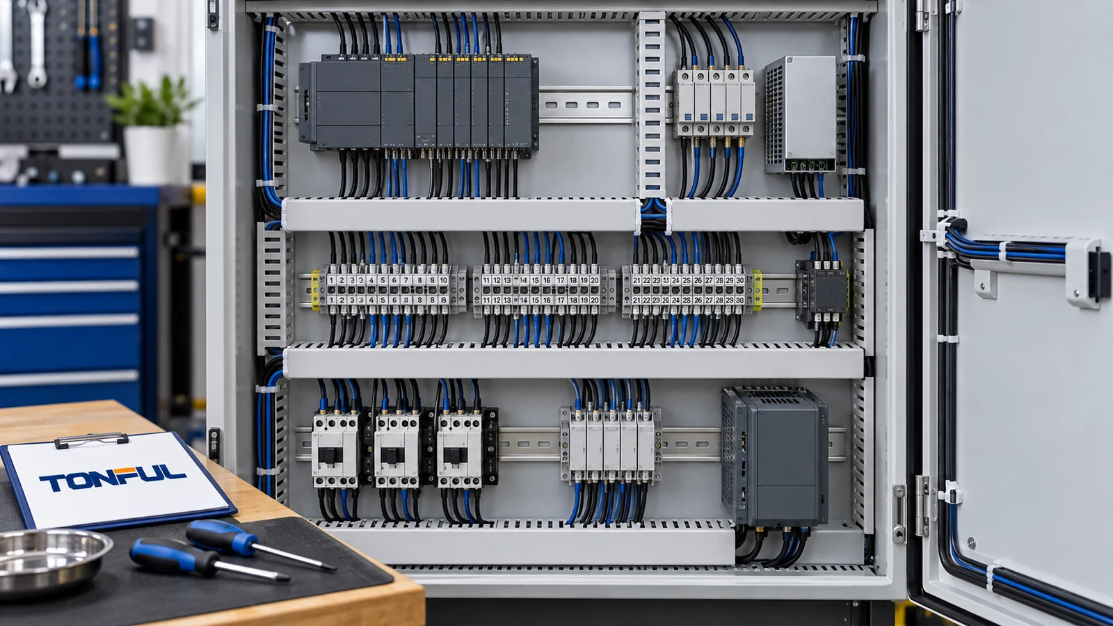
A tidy control cabinet is easier to build and service, but neatness is not the same as a sound wiring design. A tight tie can indent insulation, a loose bundle can touch a hot component, and a cable fastened across a hinged door can fatigue every time the enclosure opens. Selecting ties for a panel means deciding where wires are routed, what carries their weight and how a technician will reach a terminal later.
This guide covers cabinet-specific decisions for machine builders, panel shops and maintenance teams. It does not prescribe universal tie spacing, conductor separation or duct-fill limits; those belong to the applicable drawings, equipment instructions, electrical standard and authority for the project. For basic material and bundle-size selection, see the TONFUL cable ties buying guide.
Start With the Cabinet Wiring Plan
Read the electrical schematic, layout and wiring diagram before placing ties. Mark power conductors, control power, low-level signals, communications, protective conductors, field-entry cables and moving-door circuits. Each group can have different thermal, electromagnetic, service and identification needs. Avoid a visually appealing mixed bundle if the project design requires separation or a specific pathway. The drawing should also identify which cables may be removed or added during later commissioning.
Locate the devices that need access: terminals, fuses, power supplies, relays, drives, network switches and test points. Leave the door able to open fully and removable components able to slide out without cutting several ties. Reserve space for required bend radius and for test-probe access. A tie placed over a terminal marker can make fault-finding slower or increase the chance of a wrong-wire reconnection.
Use the approved wiring duct, rail, tray or other support system as designed. Phoenix Contact’s cabinet-routing guidance explains how ducts and wire-retaining clips keep conductors organized while preserving access for later rewiring. Ties can position short groups at transitions or entry points, but should not turn a serviceable duct into a sealed bundle that must be destroyed for one conductor change.
Securement Is Not the Same as Structural Support
An ordinary cable tie can hold conductors together or keep them at a chosen location. Supporting cable weight is a separate function with its own fixing device and installation requirements. UL Solutions’ UL 62275 application guide distinguishes cable ties and associated fixing devices evaluated for particular mechanical and environmental uses. Its detailed positioning-device guide explains why a product intended as primary support needs different evidence from one used only to secure or bundle wires.
Do not hang a heavy multicore entry cable from a tie loop around a narrow rail. Provide the specified clamp, gland, tray or bracket for weight and strain relief, then use a tie only to organize the conductors after the load is taken. When a screw-on base or other mount is involved, review both the tie and base plus the screw, panel and surface. An adhesive base must also be qualified for cabinet temperature, surface preparation and life; its adhesive may set the limit even if the tie remains strong.
Minimum loop tensile strength is not an allowable hanging load. The TONFUL tensile-strength guide explains how laboratory tie strength differs from service capacity. If a cable or conduit must be supported under an installation code, obtain the exact support designation and mounting instructions instead of extrapolating from a headline pull value.
| Cabinet location | Preferred planning question | Tie or fixing inspection |
|---|---|---|
| Wiring duct transition | Can conductors still be added and traced? | No crushed insulation or blocked duct cover |
| Field cable entry | Where is weight and strain relief taken? | Gland/clamp supports cable before tie organizes cores |
| DIN-rail device row | Are terminal labels and release tabs accessible? | Head orientation and clean tail cut |
| Hinged door | Does the harness flex through its intended loop? | Tie does not become a rigid bend point |
| Hot drive or power supply | What is the real tie-head temperature? | Material and mount fit the measured profile |
| Signal and power crossing | Does routing follow the approved EMC drawing? | No tie forces an unapproved shared route |
Select Material and Geometry for the Cabinet
Begin with the bundle’s actual diameter and any branching. The tie must engage enough teeth and hold the group without indenting insulation. Wider is not automatically better: a broad strap can cover identification and create a large contact patch on small conductors. A narrow tie may concentrate pressure and allow movement if used in the wrong location. Choose by exact part dimensions, cable-jacket condition and needed routing function.
Cabinet ambient temperature may be moderate, but local heat near a drive, resistor, transformer or power supply can be higher. Check the tie and mount’s rated operating conditions against measured hot spots and the cable jacket’s rating. Do not assume a metal tie is safer near live equipment: metal creates sharp-edge and electrical-clearance concerns and can contact terminals if poorly located. If a special flame or smoke requirement applies, request part-specific evidence; a resin color is not a certification.
For a fixed indoor panel, a standard polymer tie may be appropriate when its exact ratings match the design. Releasable designs can aid maintenance, but their locking cycle and reuse claims are part-specific. The TONFUL releasable-tie guide helps separate a tool-opened reusable design from a one-time installation. In all cases, an authorized technician should be able to identify and replace the approved SKU, not improvise with a random bag of similar-looking ties.
Labeling and traceability matter in a crowded cabinet. A marker tie can help identify a bundle or temporary test group, but it does not replace conductor identification required by the drawing. If a printed tie is specified, verify print durability, head orientation and whether text is readable after installation. The TONFUL custom-printing guide discusses identification options; the panel’s wire numbering scheme remains the controlling source.

Conceptual illustration only—not an acceptance standard or laboratory micrograph. Follow the controlled panel drawing for cable paths and support.
Protect Cables at Transitions and Doors
The transition out of wiring duct is a frequent tie location. Let conductors turn through an appropriate radius and avoid a tight head exactly at the duct edge. Check that the tie does not pull one conductor shorter than its neighbors or load a terminal. If the duct cover no longer fits, resolve fill and routing rather than cinching the wires down harder. Avoid leaving sharp cut tails facing an operator’s hand or a neighboring cable jacket.
At a hinged door, the harness needs a controlled flex loop and support points that do not pinch when the door reaches its open or closed stops. Keep tie heads away from the moving bend region. A rigidly lashed bundle can move the flex point into a termination or connector, leading to conductor fatigue. Open and close the door through its full travel during first-piece approval while checking clearance, loop shape and strain at both ends.
For field cables, preserve the specified shielding and grounding arrangement. A cable tie cannot replace a protective-earth bond, shield termination, gland or cable-clamp function. When separating noisy power and sensitive communications, follow the cabinet’s EMC design and equipment instructions; no single generic tie spacing solves signal interference. Record any route change because a visually neater rearrangement may alter a validated system layout.
Install Repeatably and Check the First Piece
Define a work instruction with approved tie SKU, position, head orientation, tool and tension setting if controlled, tail-cut method and inspection points. Use enough force to keep wires in place but not so much that the jacket is flattened. A flush-cut tool reduces sharp projections; check that it does not nick the strap. If the cabinet uses more than one tie type, segregate them by part number and label the assembly station clearly.
Inspect a first-built cabinet against the drawing before releasing a run of units. Check wiring-duct covers, accessible labels, conductor bend radius, field-entry strain relief, door travel, cable-jacket marks and loose tails. Compare the actual bundle with photographs or a golden sample, but do not let the image override the controlled drawing. Record the tie and mounting-base lot when traceability is needed to investigate repeat failures.
For production monitoring, use a practical two-column checklist rather than a form with many empty repeated cells:
| Check point | Required record |
|---|---|
| Part and revision | Tie, base/clamp, color, lot and approved drawing reference |
| Route and separation | Cabinet zone, duct or tray ID and drawing revision |
| Installation | Tool/setting, head orientation, cut-tail quality and first-piece ID |
| Cable protection | Jacket indentation, bend, entry strain relief and edge clearance |
| Door operation | Full travel, flex-loop shape and termination strain |
| Decision | Deviations, inspector, date and correction evidence |
If a tie fails inspection, contain affected cabinets and look for the actual cause: wrong part, overtension, inadequate mount, missed support or changed wire routing. Simply adding another tie can hide the defect and make service harder.

Illustrative first-piece inspection; acceptance comes from the cabinet drawing and applicable project requirements.
Maintenance and Change Control
Every later wiring change should preserve cable support, separation and access. Cut a tie without damaging the cable below it; remove the old head and tail rather than leaving debris in the panel. Reinstall the named part at the approved location, recheck door travel and update wire identification. If a different tie or base is needed, review its material, temperature and support function before substitution.
Trace recurring problems such as brittle straps, slipped heads or indented insulation to lot, tool setting, cabinet hot spot and maintenance history. Changes in cable size or quantity may invalidate the original bundle range. Changes in door hardware can shift the flex path. Make those design changes visible in the wiring diagram and work instruction, not only in a technician’s field note.
RFQ and Release With TONFUL
Send TONFUL the cabinet layout, cable schedule, bundle ranges, temperature map, mounting surfaces, door movement, material and identification needs, and customer approval criteria. Ask for named tie and fixing-device drawings, production samples, part-specific ratings and change-notification terms. The TONFUL cable-tie range supports the sourcing discussion, but no generic product page establishes approval of a particular cabinet installation.
Release the exact combination of tie, mount, tool and route after first-piece verification. A good control-panel tie installation keeps wiring organized without obscuring labels, loading terminals or preventing the next technician from working safely.
Technical Sources
- UL Solutions cable-tie application guide: UL 62275 functions and installed-use context.
- UL Solutions detailed positioning-device guide: securement versus support and fixing-device scope.
- Phoenix Contact cabinet-routing guidance: wiring ducts and maintainable cabinet routes.