
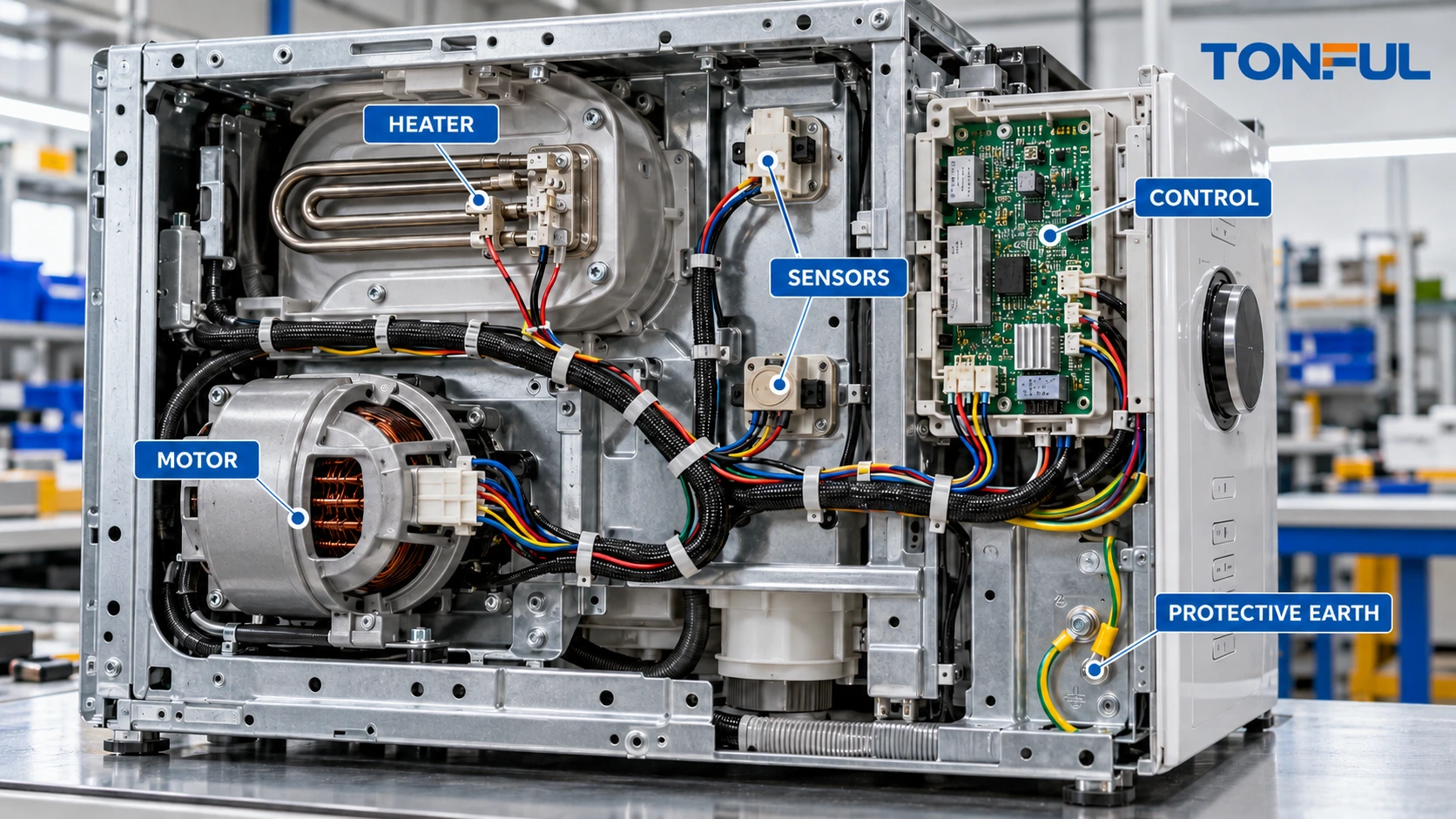
A custom appliance wire harness may connect mains input, protective earth, heaters, motors, pumps, valves, temperature sensors, switches, displays and electronic control boards inside one compact enclosure. These circuits do not share the same current, temperature, insulation, routing or fault requirements. A connector that fits physically can still be wrong for the electrical function, mating temperature, assembly sequence or service environment.
The design therefore begins with the complete appliance architecture. Every circuit needs a defined source and destination, normal and abnormal electrical condition, temperature zone, conductor and insulation, terminal interface, mechanical route and verification method. The harness must support factory assembly and service without creating pinch points, reversed connections or contact with hot and moving parts.
This guide addresses internal wire harnesses for household and similar appliances. It does not establish universal wire sizes, temperature ratings, colors, test voltages or component approvals. Those values must come from the appliance design, applicable product standard, risk assessment, component documentation and approved test plan.
Start With an Appliance Circuit and Load Map
Create a circuit schedule before choosing wire, terminals or sleeves. Separate incoming supply, protective bonding, switched heater loads, motor or pump loads, low-voltage sensors, user controls, illumination and communication lines. Record whether a device is resistive, inductive, switched electronically or interpreted by software.
| Circuit group | Design information to control | Typical harness evidence |
|---|---|---|
| Mains input | Voltage, frequency, current, polarity or line identification and protection | Controlled pinout, conductor and terminal records |
| Heater | Power, duty, switching device, hot-zone route and abnormal condition | Load-path review, temperature evidence and connection inspection |
| Motor, fan or pump | Running, starting or stalled condition; suppression and direction | Functional sequence, voltage drop and terminal-temperature evidence |
| Sensor | Sensor type, reference, polarity, range and noise sensitivity | Point-to-point map and state/response verification |
| Valve or actuator | Coil condition, polarity, suppression and duty | Output-state and connector-keying checks |
| Control/display | Supply, logic, communication, illumination and software interface | Pinout, polarity and system-function record |
| Protective earth | Attachment point, conductor, terminal, hardware and path | Bonding evidence under the approved appliance plan |
The TONFUL custom wire harness buying guide explains how circuit, branch and environment data become a manufacturable specification. Do not infer conductor capacity from appearance or copy a wire size from another appliance. Bundling, ambient heat, duty cycle, insulation, termination and enclosure ventilation all affect the released choice.
Treat Motors, Heaters, Sensors and Controls Differently
Motor and Pump Branches
Motor circuits can impose starting, reversing, braking or stalled conditions that differ from steady operation. Define the actual load profile and the switching architecture. If the harness connects a capacitor, protector, speed winding, Hall device or feedback sensor, identify each function explicitly rather than relying on color.
Terminals and connectors must be evaluated for the approved conductor, load, mating interface and temperature. Strain relief should keep motor vibration and service movement away from the conductor crimp and contact interface. Where the appliance uses replaceable motor modules, connector access and latch operation must be possible without pulling on wires.
Heater Branches
Heater circuits need special attention to local temperature, cycling, contact resistance and proximity to thermal insulation. The hottest point may be near a heater terminal, thermostat, thermal cutoff or confined connector rather than in the center of the harness. Define the temperature at each interface and the evidence used to select wire insulation, terminals, housings, sleeves and barriers.
A heater lead should not be rerouted during assembly simply because another path is shorter. Its released route may maintain spacing from polymer walls, sensors, hoses or sharp metal. If a thermal cutoff or protective device is present, document its position and connection; do not treat it as an ordinary interchangeable splice.
Sensors and Low-Level Signals
Thermistors, pressure devices, level sensors, encoders and door switches may carry low-level signals that are sensitive to contact resistance, leakage, routing or electrical noise. Specify polarity, reference return and connector cavity. Where pairing, shielding or separation is required, show it on the drawing and define termination details.
Do not apply a generic continuity-only approach to a resistance-coded sensor harness. The test fixture may need to verify the expected component, state or resistance window at controlled points, using limits supplied by the appliance program. Harness approval does not replace calibration or completed-appliance sensing validation.
Controls and Electronic Interfaces
Control boards may use low-voltage power, encoded resistor inputs, serial communication or high-impedance sensing beside mains switching. An appliance’s nominal supply voltage does not mean every connector cavity accepts that voltage. Unidentified pins must not be energized or grounded.
Define board connector orientation, cavity numbering, keying, latch direction and insertion depth. If two plugs share the same shell, add mechanical or visual error proofing where practical and verify it in the assembly process. The guide to reading wire harness drawings and connector pinouts provides a useful conflict-control method for connector end views and cavity tables.

<figcaption><em>A circuit map prevents high-load, hot-zone and low-level sensor branches from being treated as interchangeable wiring.</em></figcaption>
Divide the Appliance Into Installation Zones
One appliance can contain several environments. A cooking product may combine radiant heat, steam, grease and sharp sheet metal. Laundry equipment adds vibration, water, detergent and moving suspension. Refrigeration equipment may include condensation, cold surfaces, compressors and defrost heaters. Small appliances can place heaters, switches and controls within a very limited volume.
Create a zone map that records:
- Normal and abnormal temperature exposure.
- Moisture, steam, condensation, oil, detergent or cleaning chemicals.
- Vibration, fan airflow and motor movement.
- Sharp edges, holes, hinges and moving mechanisms.
- Required spacing or barriers from hot or energized parts.
- Assembly access, service removal and replacement path.
- Harness supports, clips, grommets, sleeves and strain relief.
Wire material names alone do not prove suitability. PVC, silicone and fluoropolymer constructions have different flexibility, abrasion, processing and temperature behavior, but the exact product evidence remains decisive. Use the PVC, silicone and PTFE wire comparison to structure that review without substituting generic material properties for a released wire specification.
Specify Connectors, Terminals and Protection as a System
For every termination, identify the connector housing, contact, seal if used, secondary lock, mating device, wire range, plating and approved applicator. A housing family may accept contacts with different wire ranges or plating. A visually similar contact is not an approved substitute.
Connector selection should address mating temperature, current path, polarization, latch access, service cycles and contamination. Direct connections to heaters, thermostats, compressors or motors may need different terminal systems from low-level board connectors. If an alternative component is proposed, use the controlled process in TONFUL’s connector selection guide and validate the complete wire-contact-housing-mate combination.
Protection also needs a location-specific purpose. A grommet protects a panel pass-through; a sleeve may provide abrasion or heat separation; a clip controls route and movement; a strain-relief feature transfers pull away from a termination. Adding generic tape cannot correct an undefined route or unsupported branch.
Build DFM Around Appliance Assembly and Service
Harness geometry must match the real assembly sequence. Establish appliance datums, branch origins, connector clocking, clip positions, breakout lengths and allowable tolerances. Check whether operators install the harness before or after motors, panels, tubs, insulation or control boards. A branch that fits a finished CAD envelope may be impossible to connect during production.
Use keyed interfaces and branch lengths to reduce cross-connection risk, but do not use deliberate tension as error proofing. Provide enough service loop for mating and authorized repair while preventing contact with fans, drums, belts, hinges or heaters. The wire harness DFM checklist helps align branch dimensions, fixture datums and assembly access.
Document retention and routing checks at critical locations. Photographs can support work instructions, but they should use a consistent viewing direction and remain linked to the drawing revision. A photograph cannot override a controlled dimension or connector table.

<figcaption><em>Routing verification checks hot surfaces, moving parts, sharp edges, branch support and connector access in the actual assembly sequence.</em></figcaption>
Validate the Harness and the Completed Appliance Separately
Harness production testing should begin with the released netlist. Verify point-to-point continuity, open/short conditions and connector orientation. Add component-state, resistance, diode, polarity, insulation-resistance or dielectric tests only when the drawing and approved plan require them. The continuity, insulation resistance and hi-pot guide explains why these tests answer different questions and cannot be substituted for one another.
The official IEC 60335-1:2020 consolidated with Amendment 1:2025 addresses safety of household and similar electrical appliances. It is appliance-level context, not evidence that an individual harness is certified, suitable for every appliance or compliant without the applicable Part 2 and project requirements.
Completed-appliance validation may need to cover heating, abnormal operation, moisture, mechanical stress, protective bonding, dielectric behavior, EMC, software-controlled protective functions and product-specific hazards. Assign responsibility for each test and identify whether the harness is monitored before, during and after conditioning.
Sample Allocation and Records
Define sample quantity, lot, configuration and allocation before testing. State whether the same samples undergo sequential conditioning or whether independent groups are used. Preserve an unconditioned reference when the plan requires comparison. Identify destructive-analysis samples and rules for invalid tests or replacements. Sample quantity and acceptance criteria must be approved by the responsible appliance program, not invented by the harness supplier.
Each record should include harness part and revision, appliance configuration, sample ID, material lots, tool/fixture IDs, instrument status, test condition, raw result, limit source, pass/fail decision, reviewer and date. Failure analysis should preserve the as-found route and identify whether damage began at a contact, crimp, conductor, support, hot surface or downstream device.
Control Production Changes and Traceability
Receiving inspection should verify exact wire, terminals, housings, sleeves, clips and labels by controlled part and lot. Production controls should cover cutting, stripping, crimping, splicing, component insertion, routing, label programming and electrical test. First-off verification is especially important after applicator change, maintenance, material change, program update or restart.
A change to wire construction, plating, connector source, clip location, branch length, heater interface, board pinout, test fixture or appliance assembly sequence can alter risk. Require documented impact review, approval, effectivity and revalidation. Lot genealogy should connect finished harnesses to relevant materials, process records and test results.
Copyable Appliance Harness Specification Record
| Field | Required entry |
|---|---|
| Appliance and configuration | Product family, model, market, revision and applicable standard set |
| Circuit schedule | Source, destination, function, electrical condition and protection |
| Zone map | Temperature, moisture, chemicals, vibration, edges and movement |
| Wire and cable | Controlled part, conductor, insulation, color and identification |
| Interfaces | Housing, contact, mating half, keying, latch and service access |
| Geometry | Datums, branches, tolerances, clips, grommets and service loops |
| Functional components | Sensors, cutoffs, resistors, diodes or suppression devices |
| Production tests | Netlist and project-defined electrical/component checks |
| Appliance validation | Test owner, sample allocation, monitoring and acceptance source |
| Change control | Notification, effectivity, revalidation and traceability |

<figcaption><em>A shared specification record aligns electrical design, appliance assembly, harness production and final product validation.</em></figcaption>
Final Release Checklist
- Every motor, heater, sensor, control and protective conductor has a defined function.
- Electrical conditions come from controlled appliance documentation.
- Thermal and environmental zones are mapped to actual routes and interfaces.
- Connector cavity views, mating halves and latch directions are unambiguous.
- Hot, moving and sharp-edge hazards have engineered routing controls.
- Assembly and service access are verified on production-intent hardware.
- Harness tests and completed-appliance tests have separate owners and records.
- Samples, limits and failure criteria are approved before validation.
- Material, process, test and shipment genealogy support traceability.
- Changes receive impact review and effective-date control.
Develop Custom Appliance Wire Harnesses With TONFUL
For a custom appliance harness quotation, provide TONFUL with the appliance configuration, circuit schedule, drawings, BOM, connector interfaces, load conditions, temperature and exposure zones, assembly sequence, test plan, demand and applicable requirements. TONFUL can review manufacturability, component control, sample documentation and production test scope within the agreed project. Final appliance safety, EMC, functional performance and market approval remain responsibilities of the completed-product program.