
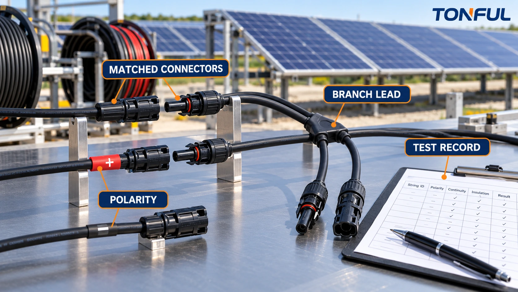
Custom solar cable assemblies connect modules, string branches, combiner equipment, disconnects, inverters and monitoring devices in long-term outdoor DC service. Their apparent simplicity can hide important interfaces: cable conductor and insulation, contact barrel, crimp process, connector housing, seal, mating connector, polarity, routing and the complete PV system voltage/current architecture.
A connector that clicks into another housing is not automatically compatible. Contact geometry, materials, plating, spring force, seals, tolerances and thermal behavior may differ even when two products look interchangeable. The cable assembly must also retain its electrical and environmental performance after factory processing, shipping, installation and years of exposure.
This guide addresses manufactured PV cable assemblies, extension leads, branch assemblies and equipment pigtails. It does not provide universal conductor size, voltage/current rating, burial permission, bend radius, torque, test voltage or service-life claims. Use the controlled system design, connector and cable documentation, applicable standards, installation instructions and approved validation plan.
Define the PV Circuit Before Selecting Components
Map the assembly’s source, destination, function and location. Record maximum system voltage, operating and fault-current inputs, polarity, conductor length, number of parallel paths, protective devices and disconnect boundaries. Identify whether the assembly belongs to a module lead, string, branch, combiner, inverter input, rapid-shutdown interface, monitoring device or another subsystem.
| Assembly type | Critical project inputs | Required evidence |
|---|---|---|
| Module extension | Mating connector, cable length, polarity and routing | Interface and polarity record |
| Branch assembly | Number of inputs, current/fault contribution and approved branch device | Controlled circuit and connector configuration |
| Combiner/inverter lead | Terminal/connector interface, conductor, gland and equipment entry | Drawing and equipment-interface approval |
| Monitoring/sensor pigtail | Signal type, shielding/pairing, sealing and pinout | Netlist and functional-interface record |
| Preassembled field cable | Route, support, exposure, identification and installation method | Installation drawing and inspection criteria |
| Service/replacement lead | Original interface, approved replacement scope and labeling | Application/effectivity record |
The TONFUL custom cable assembly buying guide provides a practical structure for cable construction, connector, pinout and performance requirements. Do not use a catalog current value as a substitute for PV string and fault analysis. The complete design must account for conductor, connector, ambient temperature, grouping, installation and protection.
Do Not Treat Look-Alike PV Connectors as Interchangeable
Connector compatibility must be defined by controlled evidence for both mating halves. Record manufacturer, series, exact part number, revision where applicable, contact, seal, cable range, assembly instructions and approved tooling. Terms such as “type,” “style,” “equivalent” or “compatible” are not sufficient engineering evidence.
The official IEC TR 63225:2019 specifically highlights incompatibility problems involving DC connectors from different manufacturers in photovoltaic systems. It is technical guidance, not blanket approval for any connector pair. The project must still follow the applicable equipment, product, installation and regulatory requirements.
Mixed-manufacturer mating can create risks that are not visible during installation:
- Different contact dimensions or spring behavior can raise resistance.
- Dissimilar plating or materials can alter wear and corrosion behavior.
- Seal compression and housing tolerances may not form the intended barrier.
- Latch engagement can feel complete while retention is inadequate.
- Thermal expansion can affect contact force or sealing differently.
- Certification or product evidence may cover only specified connector combinations.
If a substitute is proposed, do not approve it by one successful fit check. Compare drawings, materials, contacts, cable range, tooling, assembly instructions and qualification scope. Validate production-intent assemblies with defined samples and environmental/electrical conditions. Keep the approved combination in the BOM and prohibit uncontrolled mixing in production or field service.

<figcaption><em>Physical mating does not prove electrical, thermal, sealing or approval compatibility between PV connector halves.</em></figcaption>
Match Cable Construction to the Installation
Specify the exact cable standard or controlled product, conductor material, construction, cross-section, insulation/jacket, color, outside diameter and environmental ratings. The connector’s cable range must match both conductor and outside diameter because the contact barrel and cable seal control different interfaces.
Cable selection should address:
- Maximum circuit voltage and current under the approved design.
- Ambient and conductor temperature under installation conditions.
- UV, ozone, moisture and weather exposure.
- Flexibility during installation and behavior at low temperature.
- Abrasion, pulling, bending and edge contact.
- Chemical or salt exposure where applicable.
- Flame and smoke requirements assigned by the market/project.
- Conduit, tray, rooftop, floating, agricultural or other location-specific conditions.
Do not infer outdoor suitability from black color alone. UV stabilization, weathering evidence and the exact product marking matter. Similarly, “solar cable” does not automatically permit direct burial, submersion or every rooftop method. Those claims require product- and installation-specific evidence.
Where branch leads use different conductor sizes, confirm that each contact and seal supports its cable. A smaller conductor should not be justified by the connector’s nominal rating; conductor sizing and circuit protection remain system decisions.
Control Contact Crimping and Connector Assembly
PV connector reliability depends on the complete cable-contact-tool-process combination. Specify strip length, strand preparation, contact orientation, applicator or hand tool, die/cavity, setting and inspection method. Avoid nicked/missing strands, insulation inside the conductor crimp, brush outside the barrel or incomplete insertion.
Crimp qualification may use dimensional checks, pull testing, resistance and cross-section analysis according to the connector manufacturer, project specification and approved plan. Production controls should include tool identity/status, first-off verification, operator authorization and periodic checks. TONFUL’s crimp pull-force testing guide explains why acceptance limits must come from the validated wire-terminal combination rather than a universal blog value.
After crimping, insert the contact until retention is confirmed by the approved process. Assemble seals, glands, caps and secondary features exactly as specified. Verify cable-seal compression within the defined cable range and prevent contamination of contacts/seals by oil, dust or moisture.
Connector tightening, where used, requires the designated tool and controlled instruction. Do not publish or copy a generic torque. Locking caps and seals from similar product families may have different requirements.
Control Polarity, Branching and Identification
Define polarity by circuit and connector end view. Do not rely only on cable color because customers, markets and legacy designs can differ. Test every finished assembly for point-to-point continuity, polarity and open/short conditions against the released netlist.
Branch connectors need a controlled topology. Record input/output count, positive or negative function, contact arrangement, connector pair and conductor size for each leg. A branch device that physically accepts multiple leads does not establish allowable current or overcurrent protection.
Labels should identify assembly part/revision, polarity or circuit designation, lot/date and any installation orientation required by the project. Labels must remain readable for the specified environment without creating water traps, sharp edges or stress concentrations. The wire harness revision-control and traceability guide shows how effectivity and material genealogy should connect to shipped assemblies.
Design Outdoor Routing and Strain Relief
The cable assembly manufacturer controls cable length, connectors and specified protection; the PV system designer/installer controls much of the final route. Both sides need aligned requirements. Define support points, minimum slack, bend treatment, module/frame interfaces, edge protection and connector position.
Keep connectors out of standing water and avoid unsupported positions that place cable weight on the mating interface. Prevent contact with sharp module edges, roofing surfaces, loose hardware and moving trackers. Consider thermal expansion, wind-driven movement, snow/ice loads, maintenance access and animal damage according to the project location.
Cable ties or clips must be approved for their role. Bundling, positioning and primary support are different functions. A UV-resistant polymer tie should not be assumed suitable as long-term primary support without exact product and system evidence. TONFUL’s UV-resistant cable ties for solar outdoor use guide explains why some PV projects favor purpose-designed metal clips or ties.
For equipment pigtails, coordinate gland/seal, pull relief, enclosure entry and internal termination. Verify that installation torque or cable movement does not rotate the internal terminal or compromise the seal.

<figcaption><em>Outdoor routing must support cables and connectors while controlling edges, movement, water exposure and service access.</em></figcaption>
Validate the Assembly Without Overstating the Result
Production testing should verify continuity, polarity, open/short conditions and connector/cable identification. Add resistance, insulation-resistance or dielectric testing only when required by the controlled specification. The continuity, insulation resistance and hi-pot testing guide explains the different questions these tests answer.
Qualification may include mechanical retention, connector mating/unmating, sealing, temperature cycling, damp heat, UV/weathering, mechanical load, thermal behavior and post-conditioning resistance according to the applicable connector/cable/system plan. Define sample quantity, sequence, mounting, powered state, monitoring, pre/post measurements and failure criteria.
Do not use a short water-immersion demonstration as proof of long-term outdoor suitability. Connector sealing, cable weathering and complete-system installation are separate evidence categories. A passed cable-assembly test does not approve the PV array, combiner, inverter or installation.
Failure Evidence Matrix
| Symptom | Evidence to collect | Confirmation path |
|---|---|---|
| Local connector heating | Loaded drop, thermal location, contact/crimp condition and mating pair | Identify resistance source within defined measurement boundary |
| Water or corrosion | Seal condition, cable OD, assembly record, route and ingress path | Distinguish connector assembly from installation exposure |
| Intermittent output | Continuity under controlled movement, retention and contact inspection | Separate conductor/crimp, contact mate and downstream equipment |
| Reversed polarity | Netlist, end-view record, label and fixture result | Trace drawing, assembly and fixture configuration |
| Loose or cracked cable | Support spacing, bend location, abrasion and strain | Compare installed route with approved design |
| Connector separation | Latch/retention, mating evidence and cable loading | Confirm approved pair and installation method |
Production and Change Control
Receiving inspection should verify exact cable, contact, housing, seal, cap, branch component and label by part/lot. Prevent mixing of connector manufacturers or unapproved revisions through segregated storage, barcode or kitting controls and line clearance.
Process records should link cable lot, connector/contact lot, tool/die/cavity, operator, first-off inspection and electrical result to each finished lot. Changes to cable source/construction, connector, seal, tooling, branch topology, length, label or test fixture require impact review, approval, effectivity and revalidation.
Copyable Solar Cable Assembly Record
| Field | Required entry |
|---|---|
| PV circuit/application | Source, destination, function, system voltage/current inputs and location |
| Cable | Manufacturer/part, construction, size, OD, color and environmental evidence |
| Connector pair | Both manufacturers, series, exact parts, contacts, seals and approved mating scope |
| Tool/process | Strip, crimp tool/die/cavity, insertion, tightening and inspection |
| Geometry | Length, branches, labels, support assumptions and equipment entry |
| Production tests | Netlist, polarity and project-defined electrical checks |
| Qualification | Samples, sequence, environment, mechanical loads and post-test checks |
| Traceability | Material lots, tools, operator, fixture, results and shipment lot |
| Change control | Notification, effectivity, revalidation and field/application impact |
| Approval | Reviewer, scope, date and unresolved conditions |

<figcaption><em>A controlled record keeps cable, connector pair, tooling, polarity, routing assumptions and validation evidence aligned.</em></figcaption>
Final Release Checklist
- Circuit voltage, current, polarity, function and protection inputs are documented.
- Cable construction and environmental evidence match the location.
- Both connector halves and their approved mating scope are identified.
- Contact, seal, cable range and tooling form a validated combination.
- Branch topology and polarity are controlled by drawing and test fixture.
- Outdoor routing addresses support, edges, movement, water and service access.
- Production and qualification tests have defined boundaries and criteria.
- Lot records link materials, tools, assembly and electrical results.
- Substitutions and mixed connector combinations require formal approval.
- Cable-assembly evidence is not presented as complete PV system approval.
Develop Custom Solar Cable Assemblies With TONFUL
For a solar cable assembly quotation, provide TONFUL with the PV circuit/application, electrical inputs, cable specification, exact connector mating interfaces, branch topology, dimensions, outdoor conditions, labels, production tests, qualification plan, demand and applicable requirements. TONFUL can review manufacturability, component control, sample records and production testing within the documented project. Final PV system design, equipment compatibility, installation and market approval remain responsibilities of the complete project.