
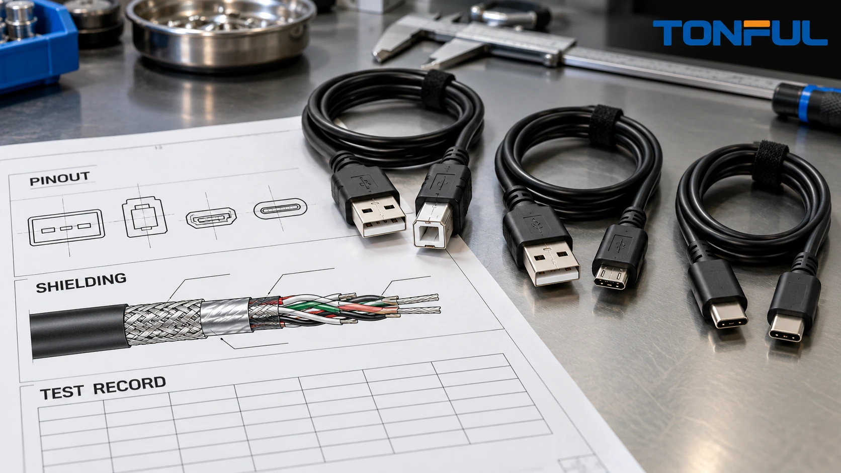
Custom USB cable assemblies cannot be specified by connector shape and length alone. A USB Type-C plug, for example, does not by itself define the data generation, supported power behavior, cable construction, active electronics or permitted logo claim. Two cables that fit the same receptacle may have different conductors, high-speed pairs, Configuration Channel implementation, shielding, current capability and validation needs.
For an OEM or equipment buyer, the first task is therefore to define what the assembly must do. The drawing and RFQ should separate mechanical interface, USB data capability, power behavior, electrical architecture, environmental exposure and acceptance evidence. This guide covers passive custom USB cable assemblies and captive USB leads. Active optical cables, protocol-conversion products and assemblies containing hubs or other functional electronics require a separate architecture and compliance plan.
Start With a USB Assembly Definition, Not a Connector Name
Record both endpoints, plug orientation, receptacle mating interface, cable direction, intended host/device relationship and whether either end is captive. Specify the exact USB data requirement rather than writing only “USB-C cable.” USB Type-C is a connector system; it does not guarantee a particular data rate, USB Power Delivery behavior or alternate-mode capability.
The controlled assembly definition should answer these questions:
- Is the assembly USB 2.0-only, a specified USB 3.x configuration, USB4-capable or intended only for power under an approved design?
- Is it Type-A to Type-B, Type-A to Micro-B, Type-C to Type-C, Type-C to a legacy connector or a captive lead?
- Is the cable passive or active, and does it require identification electronics or other embedded components?
- Which conductors, differential pairs, sideband paths, Configuration Channel connections, shields and drain wires are required?
- What power and current behavior must the complete product support, and what source/sink roles apply?
- Which specification revision, customer document and test plan control acceptance?
This architecture record should precede the general purchasing fields in a custom cable assembly buying guide. It prevents a familiar connector shell from becoming an unsupported performance promise.
Build a Controlled Connector and Pinout Matrix
A usable drawing identifies connector manufacturer, controlled part number, plug or receptacle, contact configuration, overmold or backshell, orientation datum and mating reference. It should show each endpoint as the reader sees it and state whether the view is the mating face, wire side or PCB side. Mirrored end views are a common cause of reversed pin assignments.
| Controlled field | End A | End B | Required evidence |
|---|---|---|---|
| Connector family and part number | Enter value | Enter value | Approved drawing or BOM |
| View direction and orientation datum | Enter value | Enter value | Labeled end-view drawing |
| Contact/cavity identifier | Enter value | Enter value | Manufacturer documentation |
| Circuit name and signal class | Enter value | Enter value | Controlled pinout |
| Wire, pair or shield assignment | Enter value | Enter value | Cable construction record |
| Shell/shield termination | Enter value | Enter value | Assembly drawing and sample |
| Embedded component | Enter value | Enter value | Schematic, value and orientation |
| Unused contact treatment | Enter value | Enter value | Drawing instruction |
Do not copy a pinout from a visually similar internet diagram. Legacy USB connectors, Type-C implementations, charge-only assemblies and proprietary captive interfaces may differ. If an adapter or embedded resistor is required, the BOM, schematic, value tolerance, orientation and inspection method must be controlled. The wire harness drawing and connector pinout guide provides a useful method for resolving end-view and revision conflicts.
Separate Data Pairs, Power Conductors and Control Paths
USB conductors do not all have the same design purpose. Data pairs depend on controlled geometry and termination; power and ground paths depend on conductor resistance, connector interfaces and thermal behavior; Type-C control paths establish attachment and role behavior. The assembly specification should classify every circuit before selecting conductor size or manufacturing method.
For USB 2.0 data, preserve the intended D+ and D- pair identity through cutting, stripping and termination. For higher-speed implementations, control every required differential pair, pair-to-pair relationship, shield arrangement, drain path and connector launch. Specify finished cable length and any branch or breakout geometry because these alter the transmission path. A general twisted-pair cable assembly control plan is a starting point, but the approved USB design and test plan remain controlling.
Power-path conductor selection must use the project voltage, current profile, length, allowable voltage drop, connector/contact capability and temperature conditions. Do not infer allowable current from cable diameter or connector type. For Type-C designs, document the applicable power behavior and whether the assembly requires electronically marked cable functionality. The e-marker requirement, device capabilities and negotiation behavior are architecture decisions, not optional production labels.
Control Shielding as a Complete Path
Shield performance depends on the cable construction, coverage, termination and connector transition working together. A drawing that says only “shielded cable” is incomplete. Identify foil, braid or combined construction; drain-wire use; shield continuity; shell connection; termination method; exposed length; overmold interface; and whether the shield is continuous, connected at both ends or intentionally treated differently under a controlled design.
Keep pair untwist, foil removal and shield opening as short and repeatable as the approved process allows. A long unshielded fan-out can change impedance and coupling even when continuity passes. Define strip dimensions, work-aid photographs, foil fold-back, braid preparation and shell attachment. Inspection should verify strand damage, whiskers, incomplete circumferential contact, shorts to signal contacts and variation in the connector launch.

Conceptual illustration of the cable elements and transition features that require drawing and process control; it is not a signal-integrity acceptance standard.
Design the Mechanical Assembly Around Real Use
The finished USB cable also needs dimensional and mechanical requirements. State connector datum-to-datum length, exposed lead lengths, tolerances, label location, orientation, jacket color, overmold envelope, bend direction and packaging coil. For a captive lead, define panel exit, grommet, strain relief, internal routing and retention at the equipment interface.
Overmolding can improve handling and strain distribution, but an attractive overmold does not prove pull, flex or environmental performance. Review adhesion to the connector and jacket, flash limits, knit lines, void risk, cable centering and interference with adjacent receptacles. If flex cycling, pull, torsion, insertion/extraction or environmental conditioning is required, the drawing or validation plan must identify fixtures, rate, load, cycle sequence, sample quantity and acceptance criteria.
The same discipline applies to connector sourcing. Approved genuine components, controlled alternatives and supplier substitutions should be handled through the evidence framework in choosing connectors for custom harnesses, not by comparing appearance alone.
Match Production Tests to the Failure Being Controlled
Continuity is necessary but insufficient for many USB assemblies. It can detect opens, shorts and miswires, yet it does not prove characteristic impedance, insertion loss, crosstalk, eye performance, supported power behavior or interoperability. Define production and qualification tests separately.
| Test category | What it can establish | Important controlled conditions |
|---|---|---|
| Pin-map continuity | Correct circuit routing and connection | Tested endpoints, fixture map, resistance threshold source |
| Short/open test | Isolation between specified conductors | Nets included, shield treatment, embedded components |
| DC resistance or voltage drop | Power-path and contact-path result | Test current, Force/Sense points, reference length, temperature |
| Shield continuity | Intended shell/shield path exists | Probe points and intentional isolation rules |
| Signal-integrity test | Defined transmission performance | Frequency/data requirement, fixture/de-embedding and limits |
| Functional/interoperability test | Behavior with defined equipment | Host/device set, orientation, modes and software revision |
| Mechanical test | Retention, flex or strain response | Fixture, load/rate/cycles, conditioning and failure criteria |
Use the continuity, insulation-resistance and hi-pot comparison to keep those methods distinct. Do not add insulation-resistance or dielectric-withstand testing merely because a tester supports it; apply only the controlled voltage, connections, dwell and acceptance source suitable for the assembly and embedded components.
For low-resistance power paths, record instrument range, resolution, accuracy and calibration; current level; polarity or offset-compensation method where applicable; Force and Sense locations; reference-cable subtraction rule; ambient temperature; raw and corrected result; and acceptance document. Every resistance between the Sense points remains part of the reported result.
Treat Type-C Orientation and Power Behavior as System Functions
Type-C reversibility requires the approved design to work in each applicable plug orientation. Test the required orientation combinations and record the expected data, charging and role behavior. Do not assume that a symmetric connector guarantees symmetric internal wiring or equivalent functional results.
The USB-IF USB Type-C cable and connector specification page explains that Type-C provides reversible plug orientation and scalable power/performance, and it separately describes compliance testing and conditions for certified logo use. This distinction matters: a connector type is not a declaration that every data mode, power level or alternate mode is supported.
For each Type-C assembly, control:
- Applicable USB and Type-C specification revisions.
- Passive or active cable classification.
- Required data paths and orientation combinations.
- Configuration Channel implementation and component values.
- Supported power behavior and current-carrying construction.
- Identification-electronics part, programming and traceability when applicable.
- Functional test equipment, firmware and expected results.
- Product marking and logo authorization status.
Cable approval alone does not establish compliance of the completed host, device, charger or power system. Conversely, a passing end product does not remove the need to control the cable’s drawing, components and manufacturing process.
Establish a Qualification and Production Release Plan
Allocate samples before testing. State whether tests use independent samples, sequentially conditioned samples, unaged controls or destructively analyzed samples. Define replacement rules for fixture-caused invalid tests; do not silently replace a failed sample. The approving party should justify the sample quantity using project risk, applicable specification, customer requirements and validation purpose.

Conceptual validation workflow separating sample identity, baseline results, conditioning, retest and disposition; project documents define the actual sequence and limits.
A practical release record should include:
| Record field | Required entry |
|---|---|
| Assembly identity | Part number, revision, lot and sample ID |
| USB architecture | Connector types, data capability and power behavior |
| Cable construction | Supplier part, pairs, conductors, shields and lot |
| Termination process | Equipment, tooling, settings and work-instruction revision |
| Electrical results | Pin map, shorts, resistance and shield results |
| Performance results | Applicable signal, orientation and interoperability tests |
| Mechanical/environmental results | Conditions, sequence, results and failure modes |
| Acceptance source | Drawing, customer specification or approved test plan |
| Disposition | Pass/fail, deviation, reviewer and date |
Qualification, first-article approval and routine production testing serve different purposes. Qualification challenges the approved design under defined conditions. First-article inspection confirms that an initial production-intent assembly matches controlled documents. Production testing detects manufacturing escapes within the released process. None should be described as a substitute for the others.
Control Changes and Compliance Claims
USB performance can be affected by changes that appear minor in a purchasing system. Require approval for cable supplier or construction, conductor size, shielding, connector/contact, PCB or embedded component, overmold material, strip dimensions, termination equipment, tooling, firmware, test fixture and factory location changes. Link each lot to material records, process revision, operator or machine identity and test results through the practices in wire harness revision control and lot traceability.
Keep three statements separate in supplier and marketing records:
- The assembly was built to a customer-controlled drawing.
- The assembly passed a project-specific internal or customer test plan.
- The product is authorized to make a defined USB compliance or logo claim.
One statement does not automatically prove another. Record the exact tested configuration, specification revision, report owner, model/part scope and authorization. Do not place a USB logo or claim certification merely because continuity, charging or a limited functional test passed.
RFQ Checklist for Custom USB Cable Assemblies
Before requesting a quotation, provide the supplier with a controlled package rather than a connector photo and desired length:

A controlled specification record keeps connector views, pinout, cable construction and acceptance evidence aligned before quotation and sample release.
- Assembly number, drawing revision and intended application.
- End A and End B connector manufacturer part numbers and end views.
- USB data requirement, Type-C behavior and power architecture.
- Complete pinout, embedded components and unused-contact treatment.
- Cable construction, finished length, tolerance, jacket and shielding.
- Shield/drain/shell termination and connector-transition dimensions.
- Overmold, strain relief, labels, markings and packaging.
- Environmental and mechanical exposure conditions.
- Qualification, first-article and production-test requirements.
- Sample quantity, validation ownership and acceptance documents.
- Traceability, change notification and deviation-approval rules.
- Forecast, order quantity, tooling/NRE ownership and release schedule.
TONFUL can review a project-specific USB cable assembly package for manufacturability, component control, termination access, test coverage, sample planning and production records. Send the controlled drawing, pinout, connector specifications, cable construction, performance target and validation plan for a technical and quotation review. Final USB functionality, power capability and compliance statements should remain limited to the approved configuration and supporting evidence.
—