
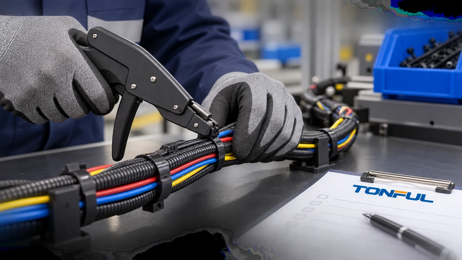
A cable tie can be the correct material and size yet still be installed badly. One operator leaves a loose loop, another indents insulation, and a third leaves a snagging tail. A tension-and-cut tool reduces variation only when qualified with the tie and bundle. Its dial is not a universal force specification.
This guide covers tool selection, finished-condition approval, cut quality and wear control for polymer cable ties in harnesses and electrical assemblies. Stainless-steel and specialized mounting ties may need different tools. The TONFUL cable ties buying guide covers material and size; here the focus is installation.
What the Tool Actually Controls
A tensioning tool grips the free strap, draws it through the locking head and may cut off the excess when its mechanism reaches a selected condition. Models differ in whether the operator controls the pull, the mechanism controls release, or an air-powered system repeats a programmed cycle. The tool can improve repeatability and reduce hand fatigue, but cannot detect every damaged jacket, wrong tie size or poor head orientation.
The HellermannTyton EVO7 instructions direct the user to select a tension setting, place the nosepiece against the tie head and pull the trigger until the tie tensions and cuts. These are instructions for named tools and compatible ties, not a generic procedure for all brands. Panduit’s tool range similarly identifies specific tie cross-sections for specific tension-and-cut tools. Confirm compatibility from both tool and tie documentation before treating a clean cut as proof of a good installation.
Do not confuse three different quantities: the tool’s dial position, the pull or cut-off force in a controlled tool test, and the pressure the closed tie applies to the actual cable bundle. They are related but not interchangeable. Head friction, strap width, material conditioning, tool geometry, bundle shape and operator alignment all influence the finished loop. Minimum loop tensile strength is a separate property measured under a defined test method, not the target installation tension. The TONFUL cable-tie strength guide provides the broader rating context; do not use its headline strength as a gun setting.
| Control variable | What it tells you | What it does not prove |
|---|---|---|
| Tool setting | Selected release or cut mechanism position | A universal force at the cable jacket |
| Tool force check | Performance in a defined test fixture | Acceptable pressure on every bundle |
| Loop tensile strength | Tie resistance in a specified strength test | Safe support load or installation tension |
| Cut-off appearance | Tail length and edge condition | No hidden insulation damage |
| First-piece inspection | Suitability of a real assembly sample | Continued control after tool wear or lot changes |
Match the Tool to the Tie and Application
Start with the approved tie part number, strap width and thickness, head design, material and bundle-diameter range. Then check the tool maker’s explicit compatibility list. A nosepiece designed for one cross-section may not seat correctly against another head; a blade may cut a thin strap cleanly but tear a thicker one. A tool advertised as “universal” still needs an assembly trial. For a broader discussion of tie families, see TONFUL’s types-of-cable-ties guide.
Choose the tool class to fit the work, not just production volume. A simple installer-controlled hand tool may suit limited rework where the operator can inspect each result. A controlled-release manual tool can help repeat the chosen setting on regular harness builds. Powered tools can reduce repetitive effort on high-volume lines but introduce air supply, pressure, cycle and maintenance variables. An automatic tool may be faster, yet a wrongly selected tie or bundle route can produce bad assemblies faster as well.
Check that the nosepiece reaches the head without levering against a connector, panel edge or cable. A bent approach can twist the head, scrape insulation or leave an uneven tail. Fix sharp-edge routing before changing tools.
Some applications need a stainless-steel tie and a metal-tie tensioning tool. Do not use the polymer-tool process as a substitute. Metal straps, locking mechanisms and edge-control methods differ, and cut edges can be hazardous. The TONFUL stainless-steel tie tool guide is a separate workflow. For any material, keep the tool, tie and installed condition named on the same work instruction.
Establish the Installation Setting on Real Bundles
Build a first-piece trial that includes the smallest and largest permitted bundle, different wire constructions, critical exits and access-limited locations. Use production-intent ties from identified lots and the intended tool model. Record the cable and jacket part numbers, not only the approximate bundle diameter. The most delicate component in the bundle can set the upper installation-pressure boundary even if the tie itself could withstand much more.
Begin with a setting that retains the route without jacket indentation, head distortion or sliding. Inspect after installation and any specified conditioning. The drawing, cable-maker instructions and approved plan must define needed force and tail limits; “looks tight” is insufficient.
Use a short setting-validation matrix:
| Trial condition | Required evidence |
|---|---|
| Minimum bundle | Engagement, head seating, no jacket indentation |
| Maximum bundle | Strap engagement, loop stability, no head damage |
| Branch or turn | No forced bend or wire pinch |
| Access-limited position | Nosepiece reaches head without levering nearby parts |
| Material or lot change | Confirm finished loop and cut remain within approved criteria |
| Post-conditioning sample | Route retention, jacket condition and cut-edge state |
Where the organization measures tool output force, use a documented fixture and conditions. HellermannTyton’s application-tooling guidance notes that tie cross-section, moisture condition, tool position, wear and cut-off speed affect the force observed in tool tests. This is why a tool check must state its reference tie and test setup. A reading taken with a different material or test fixture should not be used to claim identical pressure on production wires.

Conceptual illustration only, not a force measurement or acceptance standard. Verify the tool and tie combination on the production assembly.
Inspect a Flush Cut Without Damaging the Head
“Flush cut” should mean the finished tail is trimmed close to the head with no exposed sharp projection, according to the approved tie/tool design. It does not mean the blade may gouge the head or sever the locking pawl. An excessively short or angled cut can weaken the installed fastening; an excessive tail can snag hands, cables and clothing. Inspect the tail, head face, strap edge and surrounding cable rather than relying on the word “flush” alone.
There is no safe universal tail rule for every design. Some compatible tension-and-cut tools are expressly promoted for flush cut-off, while some tie-head geometries or customer drawings may require a defined remaining tail. Follow the exact approved part drawing and tool instruction. The older TONFUL loop-strength page advises a short retained tail in one general discussion; it should not be treated as a universal rejection of manufacturer-approved flush cutting. This conflict should be reconciled for any named part before publication or procurement approval.
Inspect the cut from the direction a hand or neighboring wire will encounter it. Do not rub an unprotected finger against a suspected sharp edge. Look for angled cuts, torn plastic, stressed heads, protruding tails and cable marks.
If cut quality drifts during a shift, stop and segregate affected work. A worn blade, loose nosepiece, changed tie lot or incorrect tool setting may be responsible. Repeatedly pulling the same tie or trimming it again with side cutters can hide a weak head or nick the cable. Remove and replace the tie where the approved work instruction requires it, then verify the bundle and electrical insulation remain sound.

Illustrative first-piece inspection; release criteria must come from the approved tie, tool and assembly documents.
Build a Repeatable Production Control Plan
Assign a tool ID, approved tie SKUs and settings to each station. Show head orientation, tool entry direction and the permitted finished condition in the work instruction. Train operators on both correct operation and visible failure signs. The first-off check should include real assemblies, not only a tool cycling demonstration. Recheck after blade replacement, tool repair, tie-material change, significant bundle change or production restart according to the risk plan.
Calibration and verification are different. Calibration may establish how a tool output relates to a reference, while an in-process check asks whether the current tool still produces an acceptable assembly. A tool with a valid sticker can still have a chipped blade; an acceptable-looking first piece does not prove a measurement device is in calibration. Record which activity was performed, its reference method, due date and acceptance source. If no numeric output specification exists, do not invent one simply to fill a form.
| Record field | Required entry |
|---|---|
| Assembly identity | Product, revision, station and bundle location |
| Tie identity | Part number, material, dimensions and lot |
| Tool identity | Manufacturer, model, serial or ID, nosepiece and blade revision |
| Setting and method | Selected setting, manual/powered mode and reference instruction |
| Test configuration | Bundle construction, min/max sample and conditioning |
| Inspection result | Retention, jacket profile, head seating and tail edge |
| Force check if specified | Fixture, reference tie, instrument, result and limit source |
| Release decision | Inspector, date, deviation, rework and closure evidence |
Sampling should reflect project risk. Document powered-tool supply conditions and settings that affect cut-off. Trend tail defects to detect blade wear before major nonconformance.
Respond to Common Defects
Loose loops can result from a low setting, poor head engagement, a tool that releases early, or a route that should have been supported elsewhere. Confirm which condition applies before increasing tension. A jacket indentation may mean the setting is too high, the tie is too narrow for the bundle, or the cable is being pulled around a bend. Correct the tie, route or setting rather than assuming a lower dial value alone solves it.
A sharp tail suggests blade wear, a mismatched head/nosepiece or misalignment. A damaged head can indicate excessive pull, wrong tie dimensions or a blade that cuts into the locking area. A tie that breaks during application could reflect a brittle or poorly conditioned lot, a stressed head or tool mismatch. Investigate tie and tool history together; do not blame the cable-tie supplier solely from a broken sample. Segregate suspect assemblies by tool ID, tie lot and build time so reinspection has a defined scope.
At tool receipt, check the nosepiece, blade and instructions. At maintenance intervals, clean the feed path, check wear and verify output with the approved assembly. Isolate powered tools before blade service, and remove trimmings from electrical work areas.
Source the Tie and Tool as a System
For a TONFUL request, provide the tie drawing, bundle ranges, cable construction, head-access constraints, production rate, required tail condition and any controlled force or retention criteria. Ask which exact tie and tool models have been tried together and request representative production samples. The TONFUL cable-tie range is a starting point for selecting a part, not proof that any third-party tool setting has already been validated.
Release the combination of named tie, lot controls, tool/nosepiece, setting, work instruction and inspected assembly. Revalidate after a meaningful change to any of those elements. Consistent installation is not a promise that every bundle receives the same force; it is a controlled process that repeatedly produces the approved retention and cable-protection outcome.
Technical Sources
- HellermannTyton EVO7 operating instructions: named-tool setup, operation and blade replacement.
- HellermannTyton application-tooling guidance: variables that affect measured tension in tool testing.
- Panduit electrical-infrastructure catalog: named tool-to-tie cross-section compatibility and controlled flush cut-off claims.