
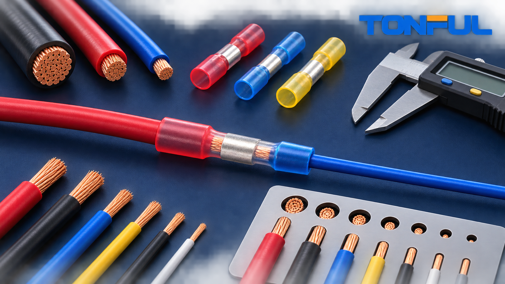

A step-down butt connector joins two conductors that do not fit the same barrel range. Selection therefore requires two decisions: the large end must fit the larger conductor, and the small end must fit the smaller conductor. A color alone is not enough because insulation thickness, strand construction, barrel geometry, and the approved crimp tool also matter.
Use the chart below as a purchasing worksheet, not as a universal product rating. Confirm the exact wire combinations in the connector manufacturer’s drawing or application specification.
TONFUL Step-Down Butt Connector Selection Matrix
The current TONFUL website describes the following family labels and wire-range combinations. It does not publish enough controlled model data to release a production size chart with part numbers, insulation-diameter limits, crimp-height windows, or certification file status. The table therefore separates published selection data from fields that TONFUL product engineering must confirm before publication or purchasing.
| TONFUL website family / series label | Large end AWG / nominal mm2 | Small end AWG / nominal mm2 | Solid / stranded restriction | Insulation OD range | Controlled strip length | Crimp die / setting | Crimp-height / pull validation | Published electrical / temperature claim | Certification status |
|---|---|---|---|---|---|---|---|---|---|
| Red heat-shrink | 22–18 AWG / 0.326–0.823 mm2 | 24–22 AWG / 0.205–0.326 mm2 | Not published; confirm conductor construction | Not published; confirm both ends | General site guidance says 6–8 mm; model drawing required | Matching approved cavities for each end; tool number not published | Model-specific limits not published; validate both ends | Website table states 600 V; temperature not stated in that table | Current certificate/file scope not published; verify before claim |
| Blue heat-shrink | 16–14 AWG / 1.31–2.08 mm2 | 22–18 AWG / 0.326–0.823 mm2 | Not published; confirm conductor construction | Not published; confirm both ends | General site guidance says 6–8 mm; model drawing required | Matching approved cavities for each end; tool number not published | Model-specific limits not published; validate both ends | Website table states 600 V; temperature not stated in that table | Current certificate/file scope not published; verify before claim |
| Yellow heat-shrink | 12–10 AWG / 3.31–5.26 mm2 | 16–14 AWG / 1.31–2.08 mm2 | Not published; confirm conductor construction | Not published; confirm both ends | General site guidance says 6–8 mm; model drawing required | Matching approved cavities for each end; tool number not published | Model-specific limits not published; validate both ends | Website table states 600 V; temperature not stated in that table | Current certificate/file scope not published; verify before claim |
| Yellow HD heat-shrink | 10–8 AWG / 5.26–8.37 mm2 | 12–10 AWG / 3.31–5.26 mm2 | Not published; confirm conductor construction | Not published; confirm both ends | Model drawing required | Approved heavy-duty tooling not published | Model-specific limits not published; validate both ends | Website table states 600 V; temperature not stated in that table | Current certificate/file scope not published; verify before claim |
| Red nylon | 22–18 AWG / 0.326–0.823 mm2 | 24–22 AWG / 0.205–0.326 mm2 | Not published; confirm conductor construction | Not published; confirm both ends | Model drawing required | Matching approved cavities for each end; tool number not published | Model-specific limits not published; validate both ends | Website table states 300 V; temperature not stated in that table | Current certificate/file scope not published; verify before claim |
These family labels and ranges come from TONFUL’s current dissimilar-wire installation guide. They are not a substitute for a controlled datasheet. Add the exact TONFUL part number, revision, dimensional limits, tooling, acceptance values, ratings, and certificate references only after product engineering releases them.
AWG and mm2 Conversion Reference
AWG-to-metric values are nominal conductor areas. They help compare sizes, but they do not prove that a particular wire fits a particular connector.
| AWG | Nominal area (mm2) | Typical selection task |
|---|---|---|
| 22 | 0.326 | Small signal or control side |
| 20 | 0.518 | Signal and light-duty circuit side |
| 18 | 0.823 | Common harness branch side |
| 16 | 1.31 | Medium branch or load side |
| 14 | 2.08 | Larger feed or load side |
| 12 | 3.31 | Higher-current feed side |
| 10 | 5.26 | Heavy feed side |
For a broader conversion reference, review TONFUL’s AWG-to-metric terminal selection guide. Always prioritize the connector’s documented conductor range over a rounded conversion. Nominal mm2 values in the selection matrix are conversions, not independently qualified metric wire ranges.
Select Both Ends Independently

Record these fields for each side:
- Conductor AWG or actual cross-sectional area
- Stranded or solid construction
- Conductor material and plating
- Strand count or construction class
- Insulation outside diameter
- Strip length
- Required tooling and die position
A nominal 18 AWG conductor can have a different outside diameter and strand behavior from another 18 AWG wire. The metal barrel must accept the conductor without strand folding, while the insulation sleeve must not be mistaken for the conductor range.
TONFUL’s wire AWG and insulation selection guide explains why conductor area and finished wire diameter must be treated separately.
Common Step-Down Combinations
Typical design requests include 22-to-18 AWG, 20-to-16 AWG, 18-to-14 AWG, and 16-to-12 AWG. These are examples of project language, not automatic approvals. The supplier must confirm that the exact connector has a barrel and tool combination for both wires.
The existing TONFUL guide on connecting dissimilar wire sizes covers installation basics. The complete step-down butt connector guide explains the product architecture.
Why Circular-Mil Area Still Matters
NASA-STD-8739.4A, section 19.12.1(c), specifies the following calculation when multiple conductors are crimped into one or both ends of a butt-splice contact:
EWS = sum of conductor circular-mil areas (CMA) x 1.25
Select the ferrule from that calculated equivalent wire size, using the next larger EWS when the result does not exactly match a single wire size. Then confirm the selected contact, wire combination, crimp tool, and setting against the contact manufacturer’s recommendations or approved engineering documentation. See the official NASA-STD-8739.4A Change 4.
Do not use simple outside diameter or the largest individual wire as the only sizing method for a multi-wire bundle.
Validate the Selection

Before production approval:
- Confirm complete conductor insertion on both ends.
- Measure crimp height with the specified method.
- Inspect for cut, folded, or missing strands.
- Perform pull testing on each end separately.
- Measure electrical resistance using an approved fixture.
- Apply environmental testing required by the end product.
TONFUL’s crimp pull-force testing guide provides a useful process overview.
RFQ Data for Correct Sizing
Send the connector supplier the large-side wire, small-side wire, insulation diameters, material, application, current, environment, strip length constraints, and available tooling. Ask for a drawing that identifies both barrel ranges and the approved crimp method.
TONFUL can review custom wire combinations and provide samples for process validation. A correct size chart should lead to a verified sample, not replace one.