
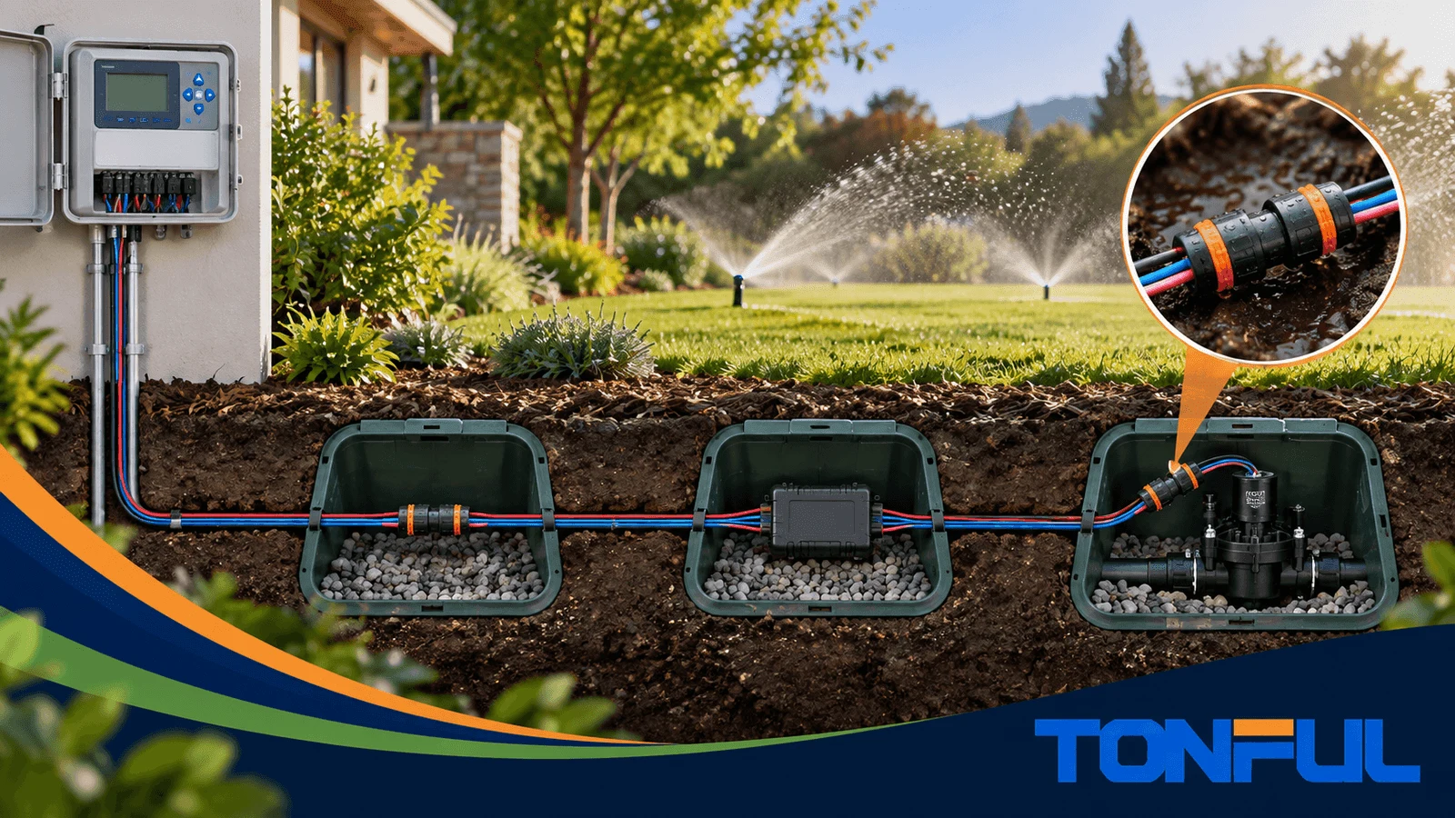
A 2-wire decoder irrigation system uses one shared cable path to carry power and communication between the controller and field decoders. Every branch, decoder, valve, sensor, and surge-protection connection depends on the integrity of that path. A corroded or high-resistance splice can therefore affect more than one station and create intermittent faults that are difficult to locate.
Connector selection must begin with the irrigation system manufacturer’s design guide. Some manufacturers specify an exact splice kit. Do not replace it with a TONFUL or other connector unless the system manufacturer and project authority approve the alternative.
Why 2-Wire Splices Need Extra Attention
Conventional multi-wire irrigation often dedicates one station conductor to each valve plus a common. A decoder system places many devices on the same two-wire path. That changes the consequence of a poor splice.
A weak connection can cause:
- Voltage loss along the path
- Communication errors
- Multiple decoder faults
- Intermittent station operation
- Surge-protection problems
- Long troubleshooting and excavation time
The connector must preserve electrical contact while limiting moisture in valve boxes, soil, and other below-grade locations.
Start with the Controller Manufacturer

Rain Bird’s ESP-LXD design guide, for example, specifies a particular 3M DBR/Y splice kit for connections to the two-wire path. That is a system requirement, not a general suggestion. A substitute can affect performance, warranty, inspection, and responsibility for failures.
Before considering any cross-reference, record:
- Controller and decoder family
- Current installation manual revision
- Required cable type and conductor size
- Approved topology and maximum path length
- Required splice kit
- Grounding and surge-protection requirements
- Project specification and local requirements
If the project permits alternative connectors, obtain written acceptance and validate them in the real wire combination.
Connector Requirements
Approved conductor combinations
The two main path wires may be joined to decoder leads, branch wires, surge devices, or cable extensions. Each splice has a different conductor count and gauge combination. Use the exact combination table rather than the connector’s broad minimum-to-maximum range.
Location and burial scope
Valve boxes are wet, dirty, and frequently below grade. A connector may need wet-location or direct-burial approval according to the actual installation. Review TONFUL’s UL 486D direct-burial guide before comparing product claims.
Electrical and communication stability
The splice should provide stable conductor contact, not merely continuity at the moment of installation. Wire preparation, spring or barrel contact, corrosion resistance, and mechanical strain all affect the path.
Surge and grounding integration
Waterproof connectors do not replace required grounding or surge-protection components. Follow the controller manufacturer’s spacing, conductor, ground-resistance, and installation instructions.
Typical Splice Locations

| Location | Typical connection | Main risk |
|---|---|---|
| Decoder connection | Two-wire path to decoder leads | Shared-path interruption |
| Valve solenoid | Decoder output to solenoid | Wet valve-box corrosion |
| Branch or loop | Main path to additional cable | Incorrect conductor bundle |
| Cable repair | Damaged path to extension cable | Tension and hidden damage |
| Surge protector | Path and grounding-related leads | Installation outside system design |
| Sensor decoder | Sensor leads and decoder wiring | Misidentification and intermittent signals |
Document every splice on the as-built drawing. Consistent connector type, installation method, and labeling reduce future diagnostic time.
When TONFUL May Be Considered
TONFUL offers waterproof wire nuts across several conductor ranges. They may be evaluated for irrigation products, private-label programs, or projects that do not mandate a proprietary splice, provided the candidate satisfies every technical and approval requirement.
A proper TONFUL evaluation package should include:
- System manufacturer acceptance
- Exact TONFUL model
- Approved conductor-combination evidence
- Wet or direct-burial certification scope
- Voltage and temperature ratings
- Installation instructions
- Samples made with the production cable
- Electrical, mechanical, moisture, and field validation plan
Use TONFUL’s waterproof connector cross-reference guide as a process framework, not as authorization to replace a specified part.
Installation Quality Controls
Prepare clean conductors
Strip to the specified length without nicking the wire. Remove any section showing corrosion or water migration. Do not allow soil or fertilizer into the contact area or sealant.
Build the approved combination
Keep conductor ends aligned and follow instructions for pre-twisting, insertion, and tightening. Confirm that the connector fully grips every conductor and that no bare copper remains exposed.
Leave service loops
Provide enough slack for future inspection and replacement. Do not hang cable weight or valve-box movement from the splice.
Test and document
Use the irrigation manufacturer’s commissioning procedure. Record path resistance or diagnostic results only when the procedure defines how they should be measured and interpreted.
TONFUL’s article on common waterproof wire nut problems can support installer training on poor combinations, incomplete insertion, and reuse.
Troubleshooting a Suspected Splice
- Review controller diagnostics and affected decoder addresses.
- Compare the fault pattern with the cable topology.
- Isolate power according to the system instructions.
- Inspect likely shared-path splices before individual valve leads.
- Look for corrosion, loose wires, damaged boxes, and standing tension.
- Replace suspect connectors rather than disturbing and reinstalling them.
- Recommission the path and update the maintenance record.
For a corroded valve-box connection, follow TONFUL’s guide on repairing corroded sprinkler valve wiring while preserving the decoder system manufacturer’s requirements.
Map the Shared Path Before Selecting a Connector
A decoder system is not simply a group of independent valve wires. The same pair can carry power and addressed communication through trunks, branches, loops, spurs, decoder leads, surge devices, and field joints. Document the topology before approving a splice. Record cable type, polarity convention, maximum path length defined by the system supplier, decoder count, branch points, grounding or surge arrangement, and every accessible connector location.
The connector must accommodate the exact bundle at each topology point. A straight two-conductor repair, a three-way branch, and a decoder lead connection are different combinations even when the individual wires have the same gauge. Confirm solid or stranded construction, insulation diameter, strip length, and whether parallel conductors must be kept in a defined orientation. Do not infer approval from shell color or from a broad advertised wire range.
| Path location | Application evidence | Connector evidence | Release decision |
|---|---|---|---|
| Main-line straight splice | Cable and system drawing | Approved two-wire combination and burial scope | Approve only within documented limits |
| Decoder branch | Decoder lead plus path conductors | Exact mixed-wire combination | Sample-install and inspect |
| Valve solenoid lead | Decoder output and solenoid wire | Manufacturer-authorized connection method | Follow decoder instructions |
| Surge/grounding device | System grounding plan | Device-specific termination requirement | Do not substitute generically |
| Repair extension | Cable identity and added joints | Two approved inline splices | Update route and service record |
Protect Signal Integrity Without Inventing a Universal Limit
Connection resistance, intermittent contact, conductor corrosion, and leakage to wet soil can all disturb system operation, but acceptable values and diagnostic methods depend on the decoder platform. A handheld continuity test may verify an isolated cable segment; it cannot prove communication margin or complete system health. Use the controller manufacturer’s approved diagnostic tools, fault codes, current readings, insulation tests, and isolation sequence.
Where resistance measurement is authorized, define the disconnected equipment, test voltage, polarity, path boundaries, conductor temperature, and reference cable length. Electronic decoders, surge devices, and modules can influence a reading if left connected. Do not use an insulation tester or high test voltage unless the system procedure explicitly allows it.
Commission by Segment and Preserve Traceability
For new work, inspect and test each path segment before connecting every branch. Record connector model, lot, installer, wire combination, strip length, valve-box or burial location, and a photograph with a consistent cable direction. Then commission the system using the controller supplier’s procedure. Save baseline current, communication, resistance, or diagnostic results only when those values are valid for that platform.
After repair, restore one isolated segment at a time. Confirm that expected decoders appear, valves respond to the correct addresses, and no new path alarm is present. A successful command to one decoder does not prove every downstream joint. Test the affected branch and representative devices beyond it.
Fault-to-Evidence Routing
| Symptom | More likely direction | Next controlled check |
|---|---|---|
| All decoders offline | Controller output, main path, protection, common trunk | Follow system startup and main-line isolation procedure |
| One branch offline | Branch joint, cut cable, local surge event | Isolate at mapped branch points |
| One decoder intermittent | Local splice, decoder lead, address/configuration | Compare local wiring and controller diagnostics |
| Fault appears when soil is wet | Insulation damage, water path, contaminated joint | Inspect wet-area segments and approved leakage test |
| Repeated surge failures | Grounding/bonding layout or protection coordination | Review manufacturer surge design, not connector alone |
Do not replace every connector based only on a communication alarm. Quarantine suspect parts when a lot issue is possible, but preserve enough evidence to identify whether the root cause is installation, cable damage, topology, grounding, electronics, or the connector itself.
Frequently Asked Questions
Can any UL 486D connector be used on a decoder system?
No. The connector must also match the wire combination, installation, system manufacturer’s requirements, and project approval. Certification alone does not override a specified component.
Why are decoder splice faults hard to find?
Many devices share one path. A fault near a branch can affect several downstream devices or appear only under certain loads and moisture conditions.
Should valve-box connectors be reusable?
Use a new connector unless the exact instructions permit reuse. Service work can redistribute sealant and weaken conductor retention.
Protect the Shared Path
The most important rule is simple: follow the decoder system design first. When alternatives are allowed, evaluate the complete connector against the approved cable, wire combinations, burial condition, surge design, and commissioning procedure.
For OEM irrigation products or approved alternative programs, share the full system requirement with TONFUL. The team can identify a candidate connector and supply documentation and samples, but final acceptance remains with the system manufacturer and project authority.
