
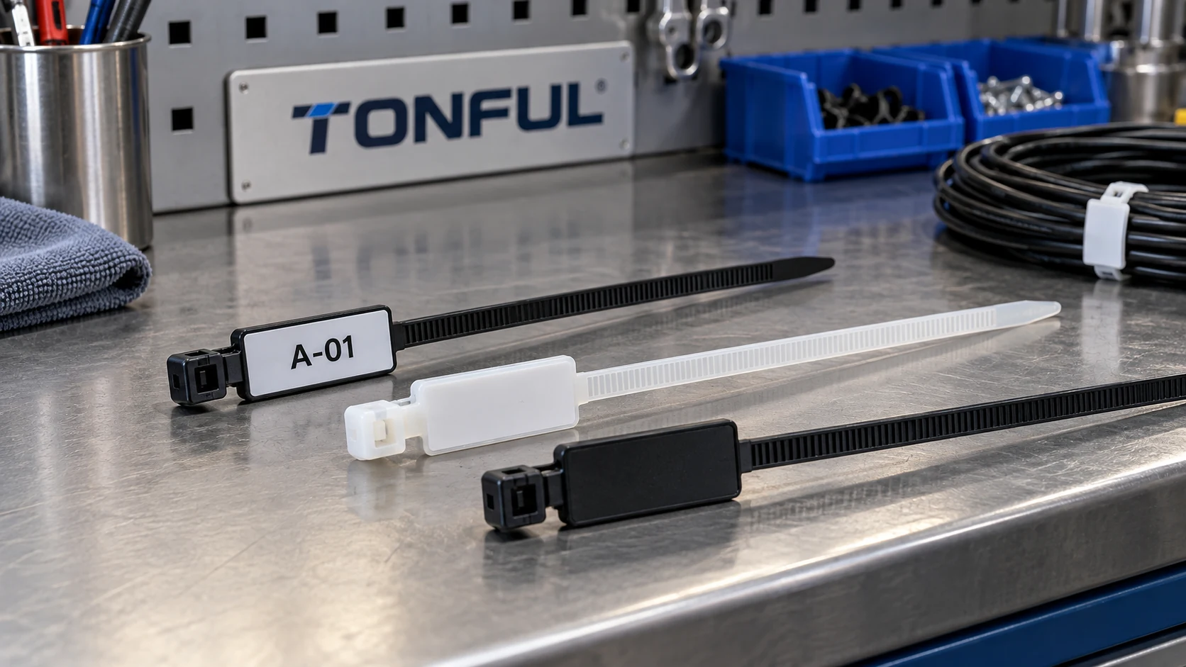
A marker cable tie adds a flat identification surface to a bundle fastener. The plate can carry a circuit ID, asset reference or serial number, but changes the part’s geometry and workflow. A label may curl, face the back of a cabinet or lose its link to a production record. Approval requires a defined label area, installed orientation and data-control plan.
This guide focuses on marker-plate ties rather than all forms of custom printing. The broader TONFUL custom-printed tie guide compares direct printing, marker plates and separate labels. Here the question is narrower: how do buyers specify, print, inspect and trace the information on a plate that is part of a cable tie?
Confirm the Marker Plate Construction
An identification tie may have a plate near its head, a flag extending from the loop or a wider section integrated with the strap. The plate can be molded in one piece with the tie or be a compatible accessory. Those architectures differ in snag risk, stiffness, available label area and replacement method. Obtain a controlled drawing of the exact candidate rather than buying from a photograph.
HellermannTyton’s identification-tie product page gives a concrete example of a PA66 tie with an identification plate and recommended printable label. Its dimensions, rating and label recommendation apply to that HellermannTyton item, not to any TONFUL part. A supplier’s label recommendation should be checked against the exact plate surface and use environment.
Record total tie length, strap width, usable bundle range, plate width and height, plate thickness, head-to-plate distance and the position of the plate relative to the loop. Include corner radius or raised border if those features reduce actual printable area. A nominal 28 mm wide plate does not provide 28 mm of reliable text width when margins, curvature or a molded lip occupy space.
The plate must not interfere with adjacent connectors, service covers, moving components or cable bend radius. On dense harnesses, a projecting flag can snag during assembly. On a curved bundle, an attached label may not lie flat. Make an installed sample on the smallest and largest approved bundle diameters and photograph it from the technician’s normal viewing direction.
Define Usable Label Area, Not Just Plate Size
The artwork should be designed within a controlled usable area. Start from the measured flat zone, then subtract margins needed for print registration, adhesive edge clearance and any protective overlaminate. For hand marking, leave enough space for the specified pen and handwriting size. For a printed label, define the label’s width, height, corner radius and placement tolerance. A label hanging over a curved edge may peel under cleaning or handling.
Do not place text where the installer grips the plate, threads the tie through its head or cuts the tail. If the plate can rotate with the tie, specify where the head and plate should face. A line of small text may be readable on a flat sample yet invisible behind the bundle after installation. The acceptance check should be performed in the real mounting orientation, at the viewing distance and lighting available during service.
| Drawing field | Required entry | Why it matters |
|---|---|---|
| Plate envelope | Maximum width, height and projection | Cabinet clearance and snag review |
| Usable print area | Flat zone after margins and borders | Font size and code feasibility |
| Label geometry | Label size, material and placement tolerance | Edge lift and print alignment |
| Tie interface | Head position, bundle range and strap path | Installed orientation |
| Service view | Access side and viewing distance | Readability without disturbing wiring |
| Change boundary | Features needing reapproval | Controls mold or artwork changes |

Conceptual area check; real dimensions and tolerances must come from the selected product drawing.
Choose the Information Architecture
A plate has limited space, so separate what must be visible from what can be retrieved in a database. A concise bundle ID may be more useful than a long description. If the identifier leads to a digital record, define the data owner, revision, lookup system and offline fallback. A code with no accessible record is not traceability.
Create a field map before preparing artwork: prefix, asset or harness ID, location, sequence, optional revision and any check digit. Identify which fields are fixed, which vary by lot and which vary for every tie. Avoid ambiguous characters such as O and 0 in a manual-read ID. If a barcode or two-dimensional symbol is used, retain human-readable text where space and project requirements permit.
Do not print a voltage, conductor role, certification or safety instruction merely because the plate fits it. Such information requires a controlled source and can be misleading when the tie is moved or replaced. A marker tie does not substitute for conductor identification, a circuit schedule or a lockout device. The TONFUL colored-tie guide makes the same distinction for color-only cues.
For multi-site purchasing, agree on one naming convention. A site code, line number and asset suffix should not be interpreted differently by two plants. Define when IDs are retired, whether they may be reused and what happens when a tie is replaced. If the marker identifies a harness during assembly, the final product record should show which ID was installed on which serial-numbered assembly.
Select the Marking Method and Substrate
Marker plates can be hand marked, directly printed or fitted with a compatible label. Hand marking can be useful for temporary or low-volume work, but ink choice and legibility must be defined. A marker described as “permanent” is not automatically resistant to the project’s solvent, heat or sunlight. Test it on the actual plate after the proposed cure or dwell time.
Printed adhesive labels need a matched facestock, adhesive, ribbon or ink, and plate substrate. Brady’s wire and cable identification guide illustrates that label materials differ by application, including outdoor and fluid exposure. Its claims apply to named Brady materials, not every label. If the plate has a textured or low-energy surface, request adhesion evidence under the relevant condition. A supplier may recommend a particular label for its plate; substitution should trigger a compatibility review.
Direct printing avoids a separate adhesive layer but may still rub, fade or crack, and the process could affect the plate surface. If laser marking or hot stamping is proposed, inspect both legibility and the tie’s mechanical behavior. A deep or overheated mark near the strap or head should not be accepted solely because it is dark. Treat marking-process changes as engineering changes when they affect performance.
Specify print contrast, character height, line spacing, orientation and approved artwork version. For variable data, control the data file as carefully as the physical printer setting. A trial should include first, middle and last printed parts, plus a restart and reject/reprint scenario. This catches shifting alignment and duplicate identifiers that a single first-piece sample may miss.
Verify Barcodes at the Installed Point
If a machine-readable code is required, choose the symbology and data payload before fixing the plate size. The symbol needs adequate dimensions and quiet zones, and the scanner must reach it after installation. Curvature, glare, dirt, overlaminate and oblique viewing can make a desk-top pass irrelevant in service. Test with the actual reader, software and lighting.
GS1’s barcode quality guidance discusses ISO/IEC 15416 for linear symbols and ISO/IEC 15415 for 2D symbols, with grading parameters defined for applicable GS1 uses. These are methods and requirements in their stated contexts, not a universal grade for every internal cable-tie label. Set the grade, verifier setup, scan-success criterion and sampling plan from the customer or system specification.
Record both print-quality verification and installed-readability checks when needed. A laboratory verifier grades the printed symbol under its method; an operational scanner confirms that the code can be reached and decoded in the actual workflow. Neither alone proves that the decoded data correctly maps to the asset. Perform a database lookup and confirm the returned record matches the physical bundle.
| Check | What to record | Possible failure |
|---|---|---|
| Symbol design | Type, payload, size and quiet zone | Code cannot fit usable area |
| Print verification | Method, aperture/illumination where applicable, grade | Poor contrast or modulation |
| Operational scan | Reader, angle, distance and installed lighting | Code hidden or reflective |
| Data lookup | Decoded ID and expected asset record | Correct print on wrong bundle |
| Reprint control | Original, rejected and replacement ID | Duplicate active identifiers |
Keep Traceability Through Production and Service
Traceability requires three linked records: what was printed, what physical tie was accepted and where it was installed. The printer log may list a sequence, but rejects, setup pieces and reprints can break a simple start-to-end assumption. Reconcile quantities: IDs issued, ties printed, ties rejected, ties installed and unused stock. If a label is applied at a separate workstation, record who or what verified the tie-label match.
At receiving, inspect the supplied part number, plate revision, packaging, lot and supplied label or print batch. Separate plain marker ties from preprinted ties so the wrong item cannot be staged. A change in resin, plate shape, adhesive or print file could affect both fit and readability. The TONFUL tie-manufacturing guide provides context for molding and lot control; marker workflows add content and print-file control.
During maintenance, a cut tie should not silently take its identity out of service. Define whether a replacement receives the same ID, a new ID linked to the old record or a separate cable marker that remains in place. A removed tie may be kept as evidence for failure analysis. If the marker is used as a tamper indicator, a unique number alone is insufficient: the seal design, issuance, custody and inspection method need separate approval.
Use a vertical release record that can be copied into a supplier or plant form:
| Record field | Required entry |
|---|---|
| Physical sample | Tie part/revision, material, color, plate dimensions and lot |
| Artwork | Source file, revision, content owner and approval date |
| Label/print system | Substrate, ink/ribbon/adhesive, printer and process revision |
| Data range | IDs allocated, printed, rejected, reprinted and accepted |
| Installation | Bundle ID, serial number, station, operator and date |
| Verification | Legibility, scan and database-match results with method |
| Exposure | Applicable abrasion, fluid, UV, temperature and aging plan |
| Disposition | Acceptance source, reviewer, pass/fail and change notice |

Illustrative record review; the pictured code is not a real production serial number.
Protect the Fastening Function
The marker area should not distract from the tie’s primary mechanical role. A large plate can press against a soft cable jacket, a protruding edge can snag and excessive tension can damage the bundle. Verify bundle range, head engagement, plate clearance, tail cut and the mounting route on the final assembly. If the tie is used for primary support rather than grouping, confirm that the exact tie and fixing device are approved for that function.
UL’s cable-tie application guidance distinguishes evaluated securing and support roles and product-specific markings. A label added to a tie does not expand its rating or automatically keep an existing certification applicable to a modified construction. Ask for the actual covered part and installation conditions. The TONFUL strength guide explains why loop-tensile data do not define installed working load.
The mechanical and identification tests should use the same production-intent construction. A label, print or marker-plate modification may need requalification if it changes geometry, material or installation. Keep baseline samples and record failure modes, not just a pass stamp. A readable plate on a tie that slips is not an acceptable assembly.
Work With TONFUL
TONFUL’s cable tie range can be screened for a marker-plate project. Send the bundle drawing, preferred plate envelope, artwork, code structure, print/label method, environment, scanning workflow and mechanical acceptance source. Ask which marker-tie configuration and marking process are currently available, then request production-intent samples and a controlled approval plan.
Approve the exact tie, plate, label or print system and data workflow together. A marker tie succeeds only when the right code stays visible on the right bundle and the fastener still performs its intended duty.