
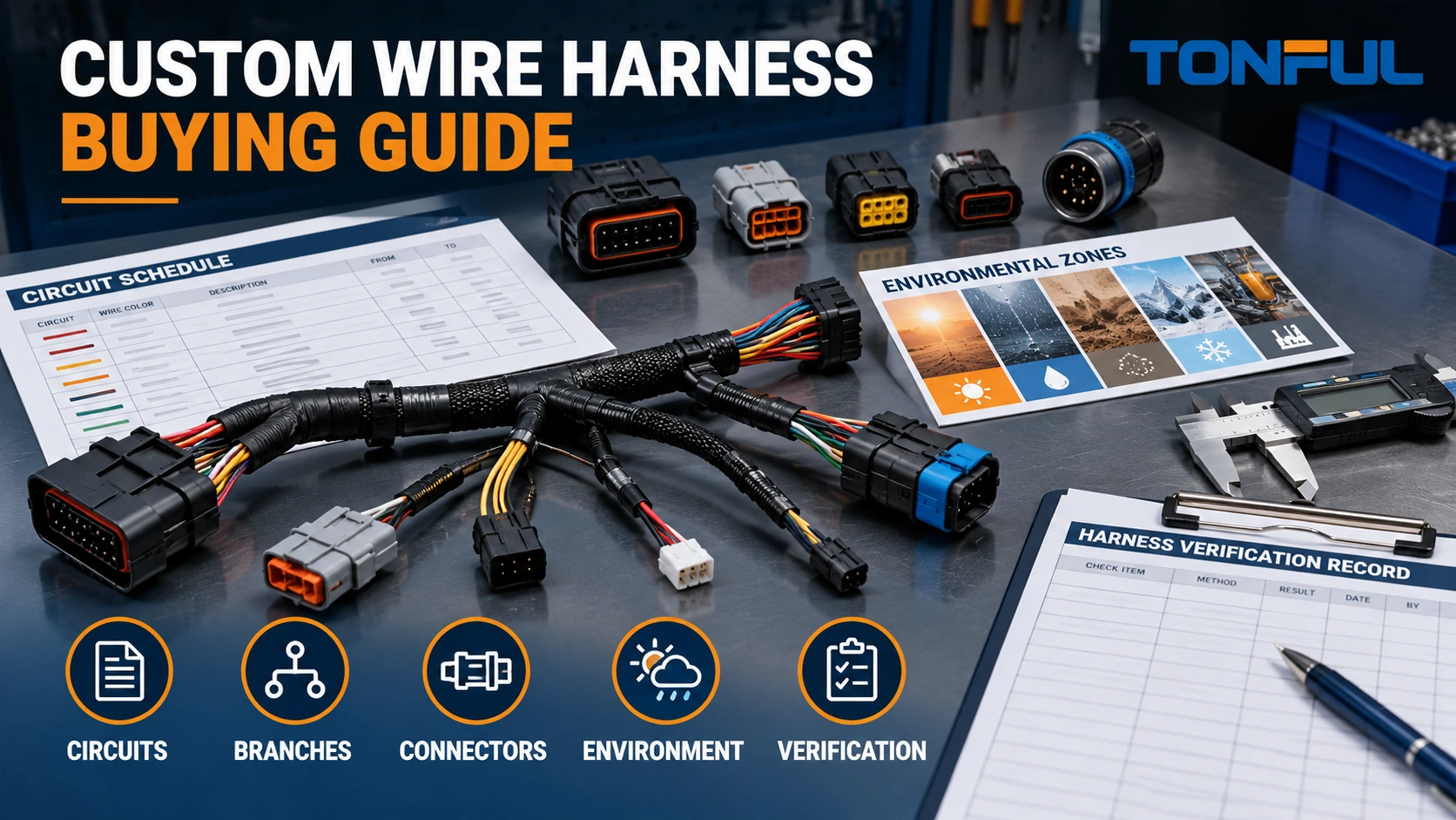
A custom wire harness should be purchased from a controlled electrical and mechanical definition, not from a sample photograph and a list of connector names. The harness must distribute power and signals to the correct destinations, fit the routing envelope, mate with every device, tolerate the installation environment and remain reproducible after the first order. Missing one of these inputs can cause miswires, short branches, incompatible terminals, abrasion or inconsistent replacement lots.
This buying guide follows the sequence an OEM, procurement team or product engineer can use before requesting a quotation: define the circuit schedule, create the branch layout, select wires and connectors, divide the route into environmental zones, establish manufacturing controls and approve the product with traceable evidence.
On this page: Circuit schedule | Branches | Connectors | Environment | Production | Approval
Build the Circuit Schedule First
Start with what every conductor must do. A useful circuit schedule identifies source, destination, electrical function, normal and abnormal load conditions, conductor requirement, isolation or pairing needs, connector cavities, grounding strategy and required test. Do not choose wire size from equipment power alone when voltage drop, starting current, duty cycle, bundling, ambient temperature and protective-device coordination also affect the design.
| Circuit field | Buyer entry | Why it matters |
|---|---|---|
| Circuit ID | Unique name used on drawing and test program | Prevents ambiguity across documents |
| Source/destination | Connector and cavity at both ends | Defines the point-to-point net |
| Function | Power, ground, analog, discrete, communication or shield | Drives routing and test needs |
| Electrical condition | Project-defined voltage, current, duty and fault case | Supports conductor and terminal selection |
| Wire requirement | Gauge/cross-section, insulation, color/marking and approved source | Controls electrical and environmental performance |
| Protection | Fuse, breaker or electronic protection reference | Keeps harness assumptions aligned with the system |
| Verification | Continuity, resistance, insulation or functional requirement | Connects design intent to evidence |
Separate high-current, noise-sensitive and communication circuits where the design requires it. Identify twisted pairs, shielded leads, drain wires and controlled grounding points. A twisted pair is not created merely by twisting two finished wires at an arbitrary pitch; pair construction, untwist at termination and routing must remain controlled where signal performance depends on them.
TONFUL’s wire AWG and insulation selection guide describes the inputs behind conductor selection. The final gauge, insulation and derating method must come from the equipment design, applicable requirements and approved calculation rather than a generic online chart.

Conceptual illustration only—not an acceptance standard or controlled project drawing. Electrical values and verification requirements must come from approved design documents.
Turn the Installation Route Into a Branch Layout
Establish Datums and Measurement Rules
Measure the equipment, not only the removed harness. Choose a primary datum and identify every breakout, connector, clip, grommet and ground point from controlled references. State whether branch dimensions run to a connector mating face, rear datum, wire exit, clip center or terminal center. Two suppliers can build different products from the same number if the measurement convention is missing.
Define tolerances according to installation need and manufacturing capability. A tight tolerance on every flexible branch can add inspection cost without improving assembly. A loose tolerance at a fixed panel connector can make installation impossible. Include connector orientation, clocking, branch exit direction and labels in the drawing rather than relying on an uncontrolled photo.
Control Routing, Bend and Service Access
Provide the harness routing envelope, nearby edges, heat sources, moving mechanisms and installation sequence. Define minimum bend requirements from approved wire, cable or component information. A service loop should have a stated purpose and allowed envelope; uncontrolled extra wire can rub, obstruct airflow or enter a moving part.
Locate clips and retainers so the harness is supported without loading connectors. Where a harness passes through a panel, define hole geometry, grommet, panel thickness and installation direction. Breakout transitions need strain distribution and protection against a tight bend at the branch root.
The TONFUL wire harness manufacturing process guide explains how a released layout reaches cutting, termination, board assembly and inspection. The drawing should support those operations without allowing the assembly board to become an uncontrolled design authority.
Select Connectors, Terminals and Seals as a System
Connector selection includes more than the plastic housing. Record the housing, terminal, secondary lock, wire seal, cavity plug, backshell, boot, mounting clip and mating component. Verify that the terminal accepts the specified conductor and insulation and that the approved crimp tooling is available. Similar-looking terminals from one family can have different material, plating, wire range or retention features.
Use complete manufacturer references where they are mandatory. If alternatives are permitted, control them through a qualified cross-reference rather than “equivalent connector” language. Compare mechanical keying, polarization, cavity numbering, latch, terminal position, current path, mating cycles, sealing architecture, materials and applicable validation.
The TONFUL automotive electrical connector range can support connector sourcing discussions, but a category listing does not prove a connector is approved for every vehicle, current or environment. Require the exact offered part and evidence.
For sealed interfaces, confirm seal-to-wire compatibility, cavity plugs for unused positions and assembly instructions. A sealed connector can lose performance if the wrong wire outside diameter, damaged seal, missing plug or poor rear strain control is used. Do not assign an assembly-level IP claim from the housing alone.
| Connector decision | Evidence to retain |
|---|---|
| Housing and mating interface | Complete part number, revision and mating reference |
| Terminal | Material/plating, wire range, drawing and approved applicator |
| Seal system | Wire OD range, cavity plug and assembly instruction |
| Cavity map | Same end-view orientation on drawing, test fixture and inspection record |
| Retention | Terminal insertion/retention method and connector-lock verification |
| Alternative source | Comparison record, sample validation and approval status |
Divide the Harness Into Environmental Zones
One harness can pass through several environments. Build a zone map instead of applying one vague “industrial” or “automotive” label to the whole assembly.
- Protected enclosure: focus on routing, terminal access, identification and electrical clearances.
- Abrasion zone: define sleeve, conduit, tape or edge protection and its start/stop points.
- Heat zone: define temperature exposure, radiant heat, nearby components and material evidence.
- Wet or contaminated zone: define connector sealing, grommets, drainage, fluid exposure and complete-assembly tests.
- Motion zone: define bend direction, moving length, speed, cycle, torsion and strain relief.
- Service zone: define labels, disconnect access, connector polarization and allowed handling.
Record operating and storage conditions separately where necessary. Include oils, fuels, coolants, cleaners, salt, UV, dust, humidity and pressure changes only when they apply. Material names alone do not establish performance; the exact construction, conditioning and test method matter.
The TONFUL wire harness protection guide compares common covering methods. Select protection by the zone’s mechanism rather than wrapping the entire harness more heavily. Excessive tape or conduit can increase stiffness, trap contamination, enlarge the bundle and complicate service.

Conceptual illustration only—not an acceptance standard or installation drawing. Zone conditions and protection must be defined by the equipment project.
Design for Repeatable Harness Production
IPC lists IPC-D-620 among its wire-harness design standards, while its document revision table identifies the current revision status. The applicable standard, revision, class, appendices and customer exceptions must be specified by the design authority; citing a standard name without that context does not complete the product specification.
Create a controlled BOM that includes manufacturer, full part number, description, quantity, approved alternates and revision-sensitive characteristics. Specify cut lengths, strip lengths, crimp tooling, splice process, labels, coverings, clips and packaging. Where the drawing conflicts with the BOM or pinout, stop release and resolve the source; production should not select the more convenient value.
Design reviews should check tool and applicator access, minimum wire lengths, terminal loading sequence, splice placement, covering installation, branch-board feasibility and inspection access. A connector that fits electrically may be positioned so close to a breakout that crimping, seal installation or repair becomes inconsistent.
Production control should link Process Flow -> PFMEA -> Control Plan -> Work Instruction -> Inspection/Test Record. Define first-piece checks after setup, tooling or material changes and extended stops. Control crimp-height measurement, applicator verification, wire preparation, terminal insertion, splice parameters and test-program revision according to project risk.
Build an Approval and Test Plan
Use the circuit schedule to generate a complete test matrix. Continuity testing should verify expected connections and forbidden shorts, not merely produce a generic “PASS.” Retain harness identity, drawing revision, test-program revision, fixture, equipment/calibration status, operator or station and result record.
TONFUL’s wire harness continuity testing guide explains point-to-point controls. Add resistance, insulation resistance, dielectric withstand, functional, communication, pull/retention, sealing, vibration, temperature or chemical tests only when required by the drawing, customer specification, qualification plan or applicable standard. These tests have different purposes and cannot substitute for one another.
For destructive tests, define sample quantity, sample allocation, conditioning, fixture, equipment range/accuracy, invalid-test rules and disposition. Pull-force testing, for example, needs the correct specimen, pull direction, speed, gripping method, failure mode and acceptance source. The TONFUL crimp pull-force testing guide provides a record framework without replacing product-specific limits.

Conceptual workflow only. The released drawing and customer-approved quality plan control actual production and acceptance.
Approve the Sample and the Production Scope
First-article approval should compare the finished sample with the released drawing, BOM, pinout and workmanship criteria. Record dimensions, connector orientation, labels, protection coverage, electrical results and deviations. A golden sample can support training and visual comparison, but it must not replace controlled documents or conceal undocumented changes.
Use clear dispositions:
| Approval status | Meaning | Purchase consequence |
|---|---|---|
| Rejected | Mandatory requirement or evidence failed | No release |
| Conditional | Defined deviation with owner, scope and closure date | Limited controlled use only |
| Sample approved | Named samples met the agreed sample review | Does not automatically approve mass production |
| Production approved | Production-intent evidence accepted for a defined revision and scope | Order only within approved scope |
Before repeat orders, require confirmation of drawing revision, approved BOM sources, tooling status, test-program revision, packaging and open changes. Lot traceability should connect finished harnesses to key materials and process/test records at the level required by the project. Change notification should cover wire, terminals, connector materials, tooling, splice process, coverings, production site and test software where relevant.
Custom Wire Harness RFQ Checklist
Provide these inputs before quotation:
- Controlled drawing, BOM, pinout and revision.
- Circuit schedule with loads, functions and verification needs.
- Equipment routing model or dimensional envelope and datum rules.
- Connector, terminal, seal, mating and approved-alternative requirements.
- Environmental zone map and protection coverage.
- Applicable workmanship standard, revision, class and exceptions.
- Qualification, first-article and production-test plan.
- Label, packaging, traceability and change-notification requirements.
- Sample quantity, forecast, order quantities and repeat-order expectations.
- Required supplier response to deviations and unresolved assumptions.
Discuss a Custom Harness With TONFUL
Send TONFUL the drawing, BOM, pinout, electrical loads, routing dimensions, connector requirements, environmental zones, test plan, quantity and packaging needs. TONFUL can review manufacturability, component sourcing and sample requirements against the exact project scope. Any certification, performance or delivery claim should remain tied to confirmed product and factory evidence rather than a generic harness description.