
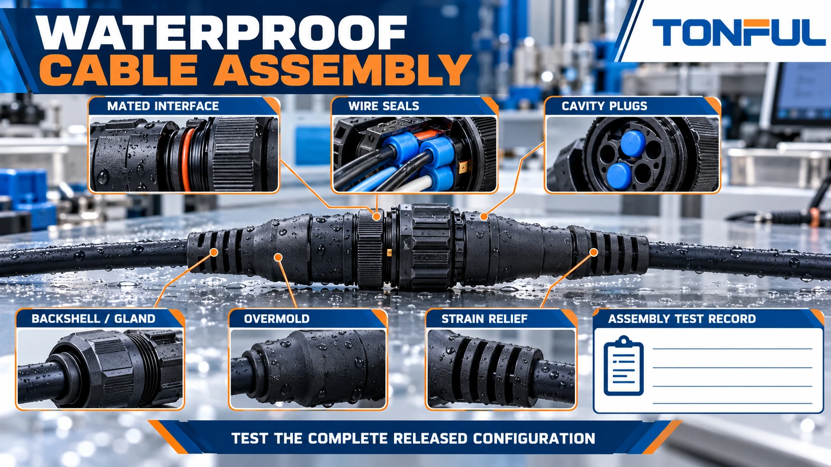
A waterproof connector does not automatically create a waterproof cable assembly. The completed path includes the mated interface, housing, terminals, individual wire seals or mat seal, unused cavities, backshell, cable jacket, overmold or gland, branch transitions and any splice. Water can enter through whichever feature is least controlled.
The word “waterproof” is therefore incomplete without a test condition and product boundary. An IP classification, connector catalog statement or supplier demonstration may apply only to a specified product configuration, mating half, mounting condition and test method. It may not cover custom wire outside diameter, damaged seals, an open cavity, a cable breakout or an overmold added by another manufacturer.
This guide helps engineers and buyers translate a wet-environment requirement into a buildable assembly, controlled production process and traceable verification plan. It does not assign a universal IP rating or immersion depth to TONFUL products without model-level evidence.
Define the Wet Environment and Failure Consequence
Map where water comes from and how long it remains. Rain, splash, washdown, condensation, temporary immersion, pressure spray, saltwater and process fluid create different stresses. Record orientation, temperature, pressure, duration, cycling, fluid chemistry, installation depth where applicable and whether the connector is mated, capped or serviced during exposure.
Then define the consequence of ingress. Moisture may create corrosion, insulation leakage, intermittent signals, tracking, short circuits, sensor drift or capillary migration along conductor strands. A low-voltage signal connector and a power assembly can require different monitoring and safety controls even in the same enclosure.
The route also matters. A cable that descends into a connector can direct water toward the rear seal. A low point can retain fluid. Repeated flexing can pump moisture through a marginal interface. The TONFUL marine harness guide explains why salt, routing, strain relief and corrosion controls must be considered with sealing rather than after it.
Understand the Assembly Sealing Boundary
Create a boundary drawing that identifies every potential path. Do not write only “IP67 connector” in the BOM.
| Sealing location | Controlled features | Typical evidence |
|---|---|---|
| Mated interface | Correct plug/receptacle, interface seal, latch and full seating | Product/application specification and mating inspection |
| Rear wire entry | Wire OD, seal part, seal condition and insertion depth | Approved combination, visual gauge and sample test |
| Unused cavity | Correct cavity plug and seating | Cavity map and inspection |
| Terminal cavity | Contact insertion, secondary lock and no seal damage | Retention/position inspection |
| Backshell/gland | Cable OD, compression, torque and strain relief | Drawing, process record and pull/flex evidence |
| Overmold | Material, adhesion, geometry, void control and process window | Sectioning/process validation and environmental test |
| Jacket/splice/branch | Compatible jacket, tubing, adhesive or potting | Material data and assembly-level test |
The official IEC 60529 consolidated edition classifies enclosure protection under defined IP Code tests. It does not state that every connectorized harness carrying an IP-looking description is approved as a completed assembly. The tested boundary, specimen condition and acceptance criteria must match the claim being made.
Match Wire Outside Diameter to the Seal
Sealed connector systems use specific relationships among contact, cavity, wire insulation and seal. AWG or mm² alone is not enough because two wires of the same conductor size can have different insulation outside diameters and surface characteristics. Request the actual minimum/maximum wire OD and the seal range from the connector manufacturer’s controlled documents.
A seal that is too loose may not compress sufficiently. A wire that is too large can damage the seal during insertion, prevent full seating or distort the housing. Insulation hardness, texture, ovality and damage also affect the interface. Do not lubricate a seal unless the connector procedure identifies an approved material and method.
For individual seals, verify that the seal is correctly oriented, positioned on the wire and captured by the insulation support without being cut or tilted. TE Connectivity’s sealed-connector application guidance visually distinguishes wire-seal position, cavity plugs, terminal locking and interface-seal condition for the covered connector family. Use it as evidence of system-specific assembly control, not as a universal instruction for other connectors.
Where the design uses separate sealed terminals rather than a complete connector system, review the TONFUL waterproof terminal guide as a starting point, then approve the exact terminal, seal, wire and housing combination from controlled product evidence.
Seal Every Unused Cavity
An empty cavity can bypass an otherwise sound rear seal. Define the populated and unused cavity map by connector variant. Use only the cavity plug specified for that housing, cavity size and seal design; visual similarity is not proof of compatibility.
Install plugs from the required direction to the defined depth and verify them before secondary locks or covers hide the rear face. TE’s AMPSEAL 16 sealing-plug guidance explains that plugs maintain sealing in unused cavities within the covered connector system. It does not authorize using those plugs in unrelated housings.
Option changes require cavity-map revision control. If a circuit is removed, the work instruction must add the correct plug. If a future circuit is added, the plug removal and terminal insertion process must avoid damaging the cavity seal. A production tester can confirm an electrical open but cannot confirm that an empty cavity is environmentally sealed.

Control the Mated Interface and Mounting
Inspect housings, keying, latch, polarization and interface seal before mating. Dirt, displaced seals, cracked housings or damaged latch features can defeat the design. Confirm full engagement using the connector’s visual, audible or dimensional criteria; “feels connected” is not a controlled method.
Mounting can load the interface. A cable tied too close to the connector may pull sideways, while unsupported mass can create vibration at the latch. Maintain the approved bend radius and provide strain relief without crushing the jacket. For panel-mounted parts, verify panel thickness, cutout, gasket and torque as applicable.
Service caps and unmated protection require separate definition. A mated connector rating does not automatically describe an open plug exposed during maintenance. If the system can operate or be washed while unmated, define the appropriate cap and procedure.
Design Backshells, Glands and Overmolds as Seal Components
Where the connector seals individual wires, a backshell may mainly provide strain relief and protection. Where a gland or overmold seals an overall cable, cable OD, jacket material and surface preparation become critical.
For glands, control insert size, nut/torque process, thread engagement and cable centering. Do not tighten until visible damage occurs. Verify retention and sealing after the specified installation process.
For overmolding, validate resin compatibility, adhesion or mechanical interlock, shot geometry, venting, pressure, temperature and cure. Voids, knit lines, contamination or jacket movement can create leakage paths. The TONFUL overmolded cable assembly guide explains why exterior appearance alone cannot prove adhesion, strain relief or environmental performance.

Build an Assembly-Level Test Plan
Test the configuration being released: actual housings, seals, contacts, wire/cable, cavity plugs, backshell or overmold, mating half and mounting condition. Connector qualification data can support component selection, but it does not replace validation of changes introduced by assembly.
A robust sequence may include identification and visual inspection, baseline continuity/insulation checks, environmental exposure, monitored or post-exposure electrical tests, drying/conditioning as defined, retention/flex tests, teardown or sectioning and final disposition. The order depends on the qualification plan; do not assume one universal sequence.
| Test-plan field | Required definition |
|---|---|
| Sample identity | Assembly part/revision, component lots and sample ID |
| Configuration | Mated/unmated, mounted/free, cavities and plugs |
| Conditioning | Water/spray/immersion, pressure, duration, orientation and cycles |
| Fluid | Composition, conductivity and temperature where relevant |
| Electrical monitoring | Circuits, voltage/current, leakage or insulation method |
| Fixture | Mating fixture, mounting, cable support and motion |
| Acceptance source | Drawing/specification/standard revision and section |
| Post-test actions | Drying, inspection, teardown, sectioning and retest |
| Failure handling | Invalid-test rule, retest authority and evidence preservation |
Do not use colored water in a casual immersion demonstration as a substitute for the approved method. Bubbles can come from trapped air rather than leakage, while a connector can retain water internally without visible bubbles. Define objective detection and acceptance criteria.
The TONFUL article on how waterproof wire connectors are tested separates product claims, sample identity, conditioning and post-test evidence. Apply the same claim-to-test discipline to connectorized cable assemblies while using the method required for the actual product.
Monitor Electrical Performance Safely
Water exposure may be combined with continuity, insulation resistance or leakage monitoring when the governing method requires it. Define which conductors are energized, grouped, grounded or monitored; protect personnel and equipment; isolate incompatible electronics. Do not apply a dielectric or insulation-resistance test merely because the assembly is described as waterproof.
Baseline and post-test values must use the same measurement boundary. Preserve raw data and environmental timing. If a failure appears only during flexing or pressure cycling, record the first event and fixture condition rather than reporting only a final pass/fail.
For power assemblies, inspect for corrosion, heating and contact change under the required load test. For data assemblies, continuity may remain correct while impedance or communication performance degrades. Choose the electrical layer that matches the failure consequence.
Diagnose Leakage Without Destroying Evidence
When a sample fails, quarantine it before drying, remating or disassembly erases the path. Photograph orientation and moisture location. Review cavity population, plug seating, seal/wire OD, terminal insertion, interface latch, gland/overmold and cable damage.
Use controlled methods such as sectional inspection, pressure-decay localization, dye only when approved, or component substitution designed by the investigation plan. Distinguish the primary ingress point from secondary migration along strands or braid. A wet connector face does not prove the interface seal was the origin.
Record the corrective-action chain: immediate containment, root-cause evidence, process or design change, revalidation and production-control update. If a seal supplier, wire OD or molding process changes, repeat the affected approval rather than relying on the previous family name.

Production Controls for Repeatable Sealing
Receiving inspection should verify exact connector, seal, plug, wire/cable and overmold materials by part and lot. Protect seals from contamination, deformation and uncontrolled shelf conditions. Control strip tools and terminal crimp so strands, insulation support and seal position match the connector specification.
If adhesive-lined tubing forms a splice cover or jacket transition, define its recovery, overlap, adhesive flow and substrate compatibility instead of treating heat shrink as a generic waterproofing step. The TONFUL heat-shrink terminal guide provides related construction context, while the assembly drawing and approved validation plan must control the actual cable-assembly application.
Use in-process checks before covers hide the rear face. Poka-yoke cavity plugs and connector variants where practical. Verify secondary locks, latch condition, cable support and required torque. Final inspection should use defined visual aids rather than generic “no damage” language.
Production leak or electrical tests require validated sensitivity and fixtures. A qualification immersion test is not necessarily practical or appropriate for every unit; conversely, a short production test may not reproduce long-duration qualification exposure. State what each test detects and maintain challenge samples or verification checks where the process requires them.
Copyable Waterproof Assembly Release Record
| Record field | Required entry |
|---|---|
| Assembly identity | Part number, revision, lot and sample IDs |
| Environment | Fluid, pressure/depth, temperature, duration and cycles |
| Connector system | Both halves, seals, contacts, plugs and documents |
| Wire/cable | Manufacturer, part, lot, OD and jacket/insulation |
| Cavity map | Populated circuits and plug part for every unused cavity |
| Rear protection | Backshell, gland or overmold construction/process |
| Mounting/routing | Orientation, support, bend and strain relief |
| Test boundary | Complete specimen and fixture configuration |
| Electrical checks | Baseline, monitored and post-test methods/results |
| Inspection/teardown | Moisture location, seal condition and section evidence |
| Acceptance source | Controlled document revision and section |
| Disposition | Pass/fail, deviation, approver and date |
Specify Waterproof Cable Assemblies With TONFUL
Send TONFUL the connector and seal system, wire/cable part and OD, cavity map, plug requirements, backshell or overmold design, mounting orientation, exposure profile, electrical monitoring and acceptance sources. TONFUL can review assembly work instructions, seal inspection points, production testability and traceability against the released configuration. Any IP or waterproof claim must remain tied to the exact tested assembly and approved evidence.