
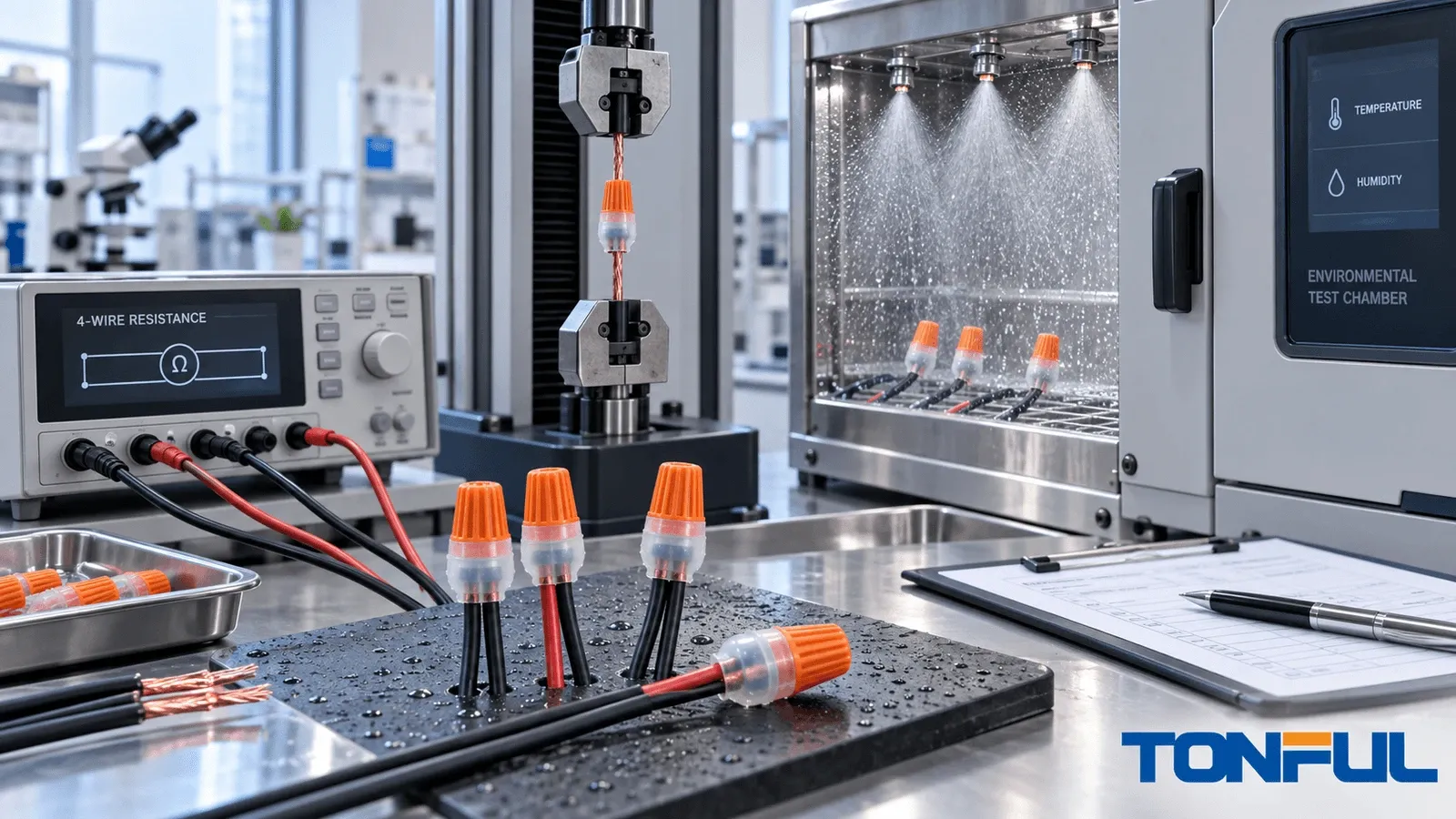
A waterproof wire nut must do more than keep visible water away from copper. Testing must show that the specified conductors remain electrically stable and mechanically retained, the sealing system survives defined exposure, and production parts remain consistent with the qualified construction. A short immersion demonstration cannot establish all of those outcomes.
This guide is specifically about sealant-filled twist-on wire connectors, commonly called waterproof wire nuts. It does not describe automotive multipin connectors, heat-shrink butt splices, cable glands, or complete cable-joint kits. Those products use different contact systems, sealing geometries, standards, and test methods.
The correct plan depends on connector type, wire combination, voltage, installation location, target market, certification scope, and customer requirements. There is no universal pull force, immersion time, resistance limit, or temperature cycle that applies to every sealed connector. Those values must come from the applicable standard, certification file, product drawing, customer specification, or approved qualification plan.
What Does Waterproof Wire Nut Testing Need to Prove?
Testing should answer four separate questions:
- Electrical: Does the joint maintain an acceptable conductive path and insulation performance under defined load and exposure?
- Mechanical: Do the wires, gripping element, housing, and seal remain secure during installation and service-related loading?
- Environmental: Does the assembled system resist the moisture, temperature, corrosion, chemicals, UV, and movement specified for its intended use?
- Production: Can the factory repeatedly build the same controlled construction and detect process drift?
UL Solutions lists UL 486D for sealed wire connector systems and UL 486G for sealed twist-on connecting devices. That distinction matters. A test report or certification for one construction, model, conductor combination, or installation method should not be treated as approval for every connector that looks similar.
The current UL 486D scope covers sealed wire connector systems using components such as caps, covers, resins, tubing, or tapes with specified connectors, and explicitly excludes twist-on-style sealed splicing connectors. The current UL 486G scope is the more directly relevant standard category for sealed twist-on connecting devices. Citing UL 486D for a twist-on product without checking the actual certification scope is therefore not sufficient.
Claim-to-Test Matrix
Marketing language must be translated into a defined claim, applicable evidence, and release boundary before a test begins.
| Claim | Evidence needed | What cannot substitute for it |
|---|---|---|
| Sealed connector | Controlled construction, specified wire assembly, sealing exposure, electrical retest, and inspection | Visual sealant fill or one short water demonstration |
| Direct burial | Exact model and installation scope supporting burial, plus project requirements | “Outdoor,” “waterproof,” wet-location use, or an enclosure IP rating |
| UL 486D | Certification evidence matching a UL 486D sealed connector system and its covered construction | UL 486G, an IP report, or a supplier’s internal immersion test |
| UL 486G | Certification evidence matching the sealed twist-on model, wire combinations, markings, and conditions | UL 486D, a similar-looking listed product, or an unverified certificate image |
| IP rating | IEC 60529-based enclosure test report identifying specimen, configuration, code, and laboratory | UL sealed-connector certification or direct-burial language |
| Approved wire combinations | Controlled model-specific combination table and installation instructions | A broad minimum-to-maximum AWG range or physical fit alone |
The IEC 60529 publication concerns degrees of protection provided by enclosures under the IP Code. An IP result applies to the tested enclosure configuration; it does not automatically establish wire retention, splice resistance, UL 486D or UL 486G certification, or direct-burial approval. Likewise, immersion demonstrations, IP tests, and UL certification are not interchangeable.
Test Approval Workflow
Use one controlled sequence so that every result remains connected to the sample and its initial condition:
Sample identification -> construction inspection -> wire-combination assembly -> baseline electrical testing -> environmental conditioning -> electrical retest -> retention testing -> authorized sectioning -> report and disposition
This order is a planning framework, not a universal standard sequence. The applicable standard or approved plan may allocate separate sample groups or change the order. Any departure must be authorized before execution and recorded in the final report.
Plan samples, conditions, and acceptance
A laboratory should freeze the test plan before exposure begins. Otherwise, sample selection, retesting, or acceptance can change after results are known. The plan should identify the exact connector part number and revision; wire manufacturer, conductor material, gauge, solid or stranded construction, insulation, and lot; preparation and installation method; sample quantity; test sequence; equipment; acceptance source; invalid-test rule; and retained evidence.
Select minimum-fill, maximum-fill, mixed-gauge, solid, stranded, and other difficult combinations when the governing document requires them. A broad AWG range does not approve every possible bundle. Allocate destructive tests separately, define conditioning and stabilization, and retain each sample’s baseline. Fixture slip, damaged leads, preparation errors, or interrupted conditioning may invalidate a result; preserve the record and follow the preapproved retest rule rather than replacing an inconvenient specimen without traceability.
Waterproof Wire Nut Test Categories
Electrical and thermal tests
Continuity is only a screening check
A continuity buzzer confirms that some conductive path exists. It does not establish low connection resistance, stable performance under load, acceptable temperature rise, insulation integrity, or long-term sealing. Qualification normally needs controlled quantitative measurements appropriate to the product and application.
Connection resistance and voltage drop
For low-resistance measurements, document test current, polarity, stabilization time, ambient temperature, instrument range, resolution, accuracy, calibration status, and exact test points. A four-wire Kelvin method reduces the effect of current-lead resistance, but every conductor, terminal, fixture interface, and contact located between the two Sense points remains part of the reported result.
Where thermal electromotive force could affect a small reading, an approved method may use current reversal or offset compensation. Record the instrument mode and calculation. State whether an equal length of unspliced reference wire is measured and subtracted. Initial and conditioned values should use the same boundaries so the change is meaningful.
An illustrative relationship is R = V / I. If a controlled path produces 0.12 V at 8 A, its equivalent resistance is 0.015 ohm, or 15 milliohms. This example explains the calculation only; it is not an acceptance limit for a waterproof connector.
Temperature rise and insulation performance
Temperature-rise testing needs the specified conductor bundle, electrical load, duty or stabilization condition, mounting orientation, enclosure condition, ambient reference, and temperature-sensor position. Heat can come from the joint, conductor, nearby equipment, or restricted airflow. Record the actual load and stabilized temperatures rather than describing a connector as simply warm.
Dielectric, leakage, or insulation-resistance tests may be required by the applicable plan. Test voltage, duration, ramp, equipment, sample condition, and discharge method must come from the governing document. A low-voltage continuity check cannot substitute for these evaluations.
Mechanical and construction tests

Conceptual illustration only – not an acceptance standard or laboratory section. Confirm the actual construction against the controlled product drawing and approved sample.
Construction inspection establishes whether test samples match the controlled design. Record housing dimensions and condition, gripping spring or contact geometry, material and lot identity, sealant type and distribution, wire-entry geometry, strip length, insertion depth, markings, and packaging. Sealant mass can be a useful process characteristic, but correct mass alone does not prove that compound surrounds the installed wire bundle without a void or migration path.
Wire-retention testing applies force in a defined direction using a suitable fixture and controlled rate. The record should include sample ID, wire combination, preparation, installation method, preconditioning, grip locations, pull direction, speed, equipment range and accuracy, peak result, displacement where required, and failure mode. The laboratory must also state whether each wire is tested individually or whether the assembled bundle is loaded according to the applicable procedure.
A numerical result without failure location is incomplete. Wire slip from the connector, conductor break outside the joint, fixture damage, housing fracture, and seal displacement represent different mechanisms. Photograph the specimen before and after testing and preserve failed parts for review.
Sealing and environmental tests

“Waterproof” is not a complete test condition. A moisture procedure must define spray, drip, immersion, water depth or pressure, duration, sample orientation, cable movement, electrical state, water composition where relevant, recovery period, and post-exposure inspection. Direct burial, a wet enclosure, temporary immersion, and an IP-code evaluation are not interchangeable claims.
A controlled sealing sequence may include:
- Verify sample identity and initial electrical/mechanical data.
- Install the exact approved wire combination using controlled instructions.
- Condition and orient specimens as required.
- Apply the defined moisture exposure.
- Perform electrical monitoring during exposure when specified.
- Repeat resistance, insulation, retention, or functional checks after exposure.
- Inspect for water paths, corrosion, compound displacement, cracking, or wire movement.
- Section only when authorized, retaining sample identity and section location.
Environmental qualification may also include thermal aging, temperature cycling, freeze-thaw exposure, humidity, corrosion, UV, vibration, chemical contact, or combined sequences. Each exposure should reflect an identified application risk and lead to a defined inspection or measurement. A sample that still looks intact may have increased resistance, reduced gripping force, embrittled housing, or sealant movement.
For burial applications, use TONFUL’s direct-burial sealed connector guide to prepare application questions, but verify the exact model’s current certification and installation scope.
How Results Should Be Recorded and Investigated
| Record field | Required entry |
|---|---|
| Sample identity | Part number, revision, connector lot, wire lot, and unique sample ID |
| Wire configuration | Quantity, gauge, construction, material, insulation, and approved combination reference |
| Installation | Strip length, preparation, tool or torque method, operator, date, and work-instruction revision |
| Equipment | Model, range, resolution, accuracy, calibration status, fixture, and software version |
| Test condition | Load/current, polarity, temperature, humidity, orientation, exposure, duration, and recovery |
| Measurement | Force/Sense points or grip locations, raw result, corrected result, initial value, and change |
| Failure evidence | Symptom, first occurrence, failure mode, photographs, retained sample, and teardown reference |
| Acceptance | Standard clause, drawing, certification file, customer specification, or approved test plan |
| Disposition | Pass/fail, invalid-test decision, deviation, reviewer, date, and corrective-action number |
A failed test should trigger containment before explanation. Quarantine affected samples and potentially related lots, preserve the original setup and data, review material and process traceability, then compare retained samples. Root-cause confirmation may require dimensional inspection, resistance mapping, pull testing, seal examination, material analysis, or a controlled reproduction.
Do not claim a cause from appearance alone. Correlate resistance changes, pull curves, exposure logs, dimensions, material lots, sealant distribution, photographs, and teardown evidence. Confirm the mechanism and update the PFMEA, control plan, work instruction, inspection record, or supplier corrective action as appropriate.
Qualification, Certification, and Production Control
Qualification evaluates production-intent samples against a defined plan. Certification evaluates the stated construction and scope under a third-party program. Production control monitors whether shipped parts continue to match that construction. These activities support one another but are not substitutes.
Routine factory checks may include incoming material identity, housing dimensions, gripping-element presence, sealant condition or fill control, lot marking, packaging, first-piece verification after setup or material change, and periodic functional tests. The control plan should define sample frequency, acceptance criteria, reaction plan, equipment status, operator authorization, nonconforming-product control, and lot traceability.
Claims such as “100% tested” must name the characteristic checked on every unit. A camera confirming component presence is not a 100% sealing test. A fill-mass check is not a complete electrical test. Buyers can use TONFUL’s waterproof wire nut manufacturer audit checklist to connect test evidence to manufacturing controls.
Supplier Evidence Checklist
Before approval, request:
- Current model drawing, revision, and bill-of-material controls
- Approved conductor-combination table and installation instructions
- Applicable certification record and exact covered scope
- Qualification plan, sample matrix, raw results, failure modes, and approvals
- Measurement equipment and calibration evidence
- Production control plan, sampling, reaction plan, and traceability method
- Change-notification rules for resin, spring/contact, sealant, tooling, process, and site
- Production-intent samples made with the proposed construction
Use TONFUL’s waterproof wire nut selection guide to define the wire bundle and environment, the waterproof connector standards guide to separate test claims, and the visual inspection guide to prepare receiving criteria.
Technical Sources and Evidence Boundaries
- UL Solutions Connector Certification Services identifies wire-connector standard categories, including UL 486D and UL 486G.
- UL 486D – Sealed Wire Connector Systems provides the official scope and states that it does not apply to twist-on-style splicing sealed wire connectors.
- UL 486G – Sealed Twist-On Connecting Devices provides the relevant standard scope for sealed twist-on devices.
- UL Product iQ is the official database resource for checking specific UL certification information, guide information, model scope, and related identifiers.
- IEC 60529 – Degrees of Protection Provided by Enclosures defines the IP Code for enclosure protection; it is not a substitute for sealed wire-connector certification.
These sources define scopes and verification paths, not TONFUL-specific certification claims. Before publication of a model claim, match the company, file or certificate identifier, model designation, wire combinations, conditions of use, and current database record.
Work With TONFUL
TONFUL supplies waterproof wire connectors for B2B sourcing and OEM/ODM projects. Share the connector type, complete wire combinations, conductor construction, voltage, installation location, environmental risks, target market, and required approval documents. TONFUL can identify candidate products and prepare samples for your controlled evaluation. Review the current TONFUL waterproof wire nut range before submitting the application data.