
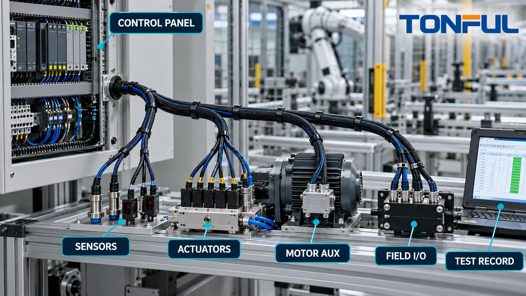
An industrial control harness is the physical interface between a machine’s control panel and its field devices. It may carry low-level sensor signals, valve and relay outputs, motor or brake circuits, communication pairs, protective bonding and auxiliary power through the same machine zone. Treating all branches as interchangeable “wires” creates noise, heating, maintenance and safety risks.
A reliable design begins with circuit function and installation conditions, not connector appearance. Each path needs defined voltage/current or signal behavior, source and destination, conductor construction, insulation, connector interface, shielding or bonding, routing, movement, environment and acceptance test. The finished harness must also be serviceable by technicians who may replace one device under production pressure.
This guide covers custom harnesses installed within industrial machinery and automation equipment. It does not assign universal conductor sizes, colors, separation distances, test voltages or environmental ratings. Those requirements must come from the machine design, risk assessment, applicable standards, component documentation and approved project plan.
Map Every Control Function Before Selecting Hardware
Build a circuit schedule that identifies power feeds, returns, digital inputs, analog sensors, encoder channels, communication buses, solenoids, contactor/relay coils, brakes, motor auxiliaries, protective bonding and spare circuits. Record normal and abnormal electrical conditions where the design requires them.
| Circuit group | Key design inputs | Common verification |
|---|---|---|
| Discrete sensor | Supply, output type, polarity, reference and diagnostic state | Pinout, switching state and short/open behavior |
| Analog sensor | Signal range, reference, shield and ground architecture | Offset/noise and channel identity |
| Encoder/network | Pairing, impedance where controlled, shield and termination | Pair map and system-level communication test |
| Solenoid/relay | Coil voltage, current, suppression and polarity | Load function and suppression orientation |
| Motor/brake auxiliary | Starting or switching behavior, temperature and routing | Voltage drop, temperature and functional sequence |
| Protective bonding | Conductor, termination, attachment and path | Bonding test per approved equipment plan |
The TONFUL guide to reading harness drawings and pinouts shows how connector views, cavity tables and wire IDs should agree. Never energize an unidentified cavity or infer a circuit from wire color alone.

<figcaption><em>Functional grouping should be established before wire, shielding, connectors and routing are released.</em></figcaption>
Define the Machine and Panel Boundary
State where the harness begins and ends: internal panel terminals, bulkhead connectors, distributed I/O, junction boxes, field devices or removable machine modules. Record which side supplies mating hardware, cable glands, terminal blocks, strain relief and protective earth interfaces.
For panel connections, define connector orientation, keying, accessible service clearance, mating cycles and whether disconnecting one plug removes energy from every contained circuit. Avoid combining incompatible power, signal or safety functions in one connector merely to reduce part count unless the architecture and component ratings explicitly support it.
IEC lists IEC 60204-1:2016+AMD1:2021 as the consolidated edition for electrical, electronic and programmable electronic equipment of applicable machines, beginning at the connection point to the machine electrical equipment. It is a machine-level standard, not proof that one harness is compliant or safe by itself. Confirm the edition, jurisdiction and equipment scope in the project.
Select Wire and Cable by Circuit and Environment
Conductor area must support the actual load, protection, length, allowable voltage drop, temperature, bundling and installation method. Low-current control circuits still need conductor constructions compatible with terminals, movement and service handling. Do not select every branch from one AWG table.
Insulation and jacket selection should consider cabinet and field temperature, oil, coolant, cleaning chemicals, moisture, abrasion, flexing, UV where exposed and flame requirements. The TONFUL PVC, silicone and PTFE wire comparison explains why polymer names alone do not prove the required rating or termination compatibility.
For moving axes, drag chains or robotic joints, define bend radius, torsion, travel, acceleration, cycles and support. A flexible conductor is not automatically a continuous-flex cable. Fixed-machine branches and dynamic branches may require different constructions even when they carry the same signal.
Segregate Power, Signal and Communication Paths
High-current switching and variable-speed drives can disturb low-level analog, encoder and network circuits. Control the physical route, pair construction, shield architecture and reference/ground path from the system design. Do not publish one universal separation distance; panel geometry, voltage, current edge rate, cable construction and applicable requirements all matter.
Maintain twisted pairs through breakout and termination as required by the connector/cable design. The TONFUL twisted-pair cable assembly guide covers pair identity, untwist and shield-control evidence. Avoid using an unpaired return for a differential or noise-sensitive circuit unless the approved architecture requires it.
Shield treatment needs an explicit drawing: shield type, drain wire, termination end or ends, 360-degree clamp or pigtail, bonding surface and insulation boundary. “Connect shield to ground” is incomplete because uncontrolled parallel paths can create noise or fault-current concerns.
Choose Connectors for Field Service and Error Prevention
Connector selection should match voltage/current, contact system, conductor range, cavity count, environmental exposure, vibration, mating frequency and service access. Keying and coding reduce wrong mating only when all variants are controlled. Similar housings may accept different terminals, seals or secondary locks.
For sensor and actuator branches, consider whether molded cordsets, circular connectors, rectangular industrial connectors or discrete housings fit the maintenance strategy. A quick disconnect can speed service but adds interfaces and potential ingress points. A hardwired pigtail removes one interface but may increase replacement time.
Use controlled component numbers and application specifications. The TONFUL connector-selection guide explains why contact, housing, seal, wire and tooling form a system. Verify insertion, retention, secondary locking and mating with production-intent samples.
Control Branch Geometry, Supports and Service Loops
Define datums for overall length, branch location, clip position and connector orientation. State whether dimensions are free-state or fixture-held. Harness-board tooling should reproduce geometry without stretching branches or forcing connector clocking.
Support the harness so connector terminals do not carry cable weight. Place clips and ties where they restrain movement without crushing jackets or concentrating flex at splice, gland or connector edges. Protect routes near sheet metal, moving mechanisms, hot surfaces and maintenance access points.
Service loops should be intentional. Too little slack transfers installation tolerance into terminals; excessive slack can enter pinch zones or obstruct panels. Define the loop location and envelope rather than adding an uncontrolled length allowance.
Design for Installation and Troubleshooting
Use durable labels and circuit IDs that remain readable in the operating environment. Coordinate device tags, connector IDs, wire numbers and drawings. A technician should be able to identify a disconnected branch without tracing every conductor manually.
Where modules are replaceable, make wrong reconnection difficult through connector coding, branch length, labels and routing. Provide test access only where the system design permits safe measurement. Do not expose energized conductors or encourage piercing insulation as a normal diagnostic method.
Document safe isolation and verification at the equipment level. Harness acceptance does not establish machine safety, emergency-stop performance, protective bonding or functional-safety compliance. Those depend on the completed machine architecture and validated protective functions.
Validate the Complete Harness
Continuity testing should compare every circuit with the released netlist and detect prohibited shorts. Verify component orientation for diodes, suppression devices, resistors, LEDs or polarized sensors. Record harness ID, tester program, adapter and result.
Add resistance, insulation resistance, dielectric withstand, loaded voltage drop or bonding tests only when the controlled plan defines circuits, method, equipment, limits and safety. The TONFUL continuity, insulation-resistance and hi-pot guide separates these tests. A continuity pass does not prove contact resistance, insulation withstand or load performance.
Functional testing should exercise sensor states, actuator commands, interlocks and diagnostic behavior at the appropriate integration level. Bench testing can confirm a harness path or component, but only machine-level validation proves interaction with PLC/I/O configuration, drives, safety controls and grounding.
Environmental validation may include vibration, flex, temperature, humidity, fluid exposure or ingress according to the application. Record sample allocation, mounting, powered state, monitoring, pre/post results and failure criteria. Do not invent a generic “industrial grade” test profile.

<figcaption><em>Harness-level electrical evidence should be linked to the released netlist, fixtures and machine-integration plan.</em></figcaption>
Production Controls and Change Management
Receiving inspection should verify exact wire/cable, connector, terminal, seal, clip, label and protection materials by part and lot. Control cutting, stripping, crimping, splicing, shield termination, routing and label programming through released instructions.
Use first-off checks after setup, tool change, material change, maintenance or restart as defined by the control plan. Maintain calibration and tool status, but also verify the correct applicator, die/cavity, program and connector variant. Error proofing should be challenged periodically with known wrong conditions where safe and practical.
Changes to devices, I/O architecture, connector source, cable construction, shielding, software/test program or machine routing require impact review. The approved harness baseline and genealogy should identify which finished machines or spare parts received each configuration.
Copyable Industrial Harness Specification Record
| Field | Required entry |
|---|---|
| Equipment/application | Machine, module, location and service environment |
| Circuit schedule | Source, destination, function, electrical condition and protection |
| Wire/cable | Controlled part, conductor, insulation/jacket and movement class |
| Connector interface | Housing/contact/seal, keying, mating half and service cycles |
| Signal integrity | Pairing, impedance if specified, shield and grounding/bonding |
| Geometry | Datums, lengths, breakouts, clips, orientation and service loops |
| Protection | Loom, conduit, gland, abrasion, heat and fluid controls |
| Tests | Netlist, resistance/withstand/bonding/function as specified |
| Evidence | Sample plan, instruments, fixtures, results and acceptance source |
| Change control | Notification, effectivity, revalidation and traceability |
Final Release Checklist
- Circuit schedule separates power, signal, communication and protective functions.
- Connector views and cavity maps are unambiguous.
- Wire/cable is approved for load, environment, termination and movement.
- Shield and reference/ground treatment is drawn, not implied.
- Branch geometry, supports and service loops fit the machine envelope.
- Labels align with equipment drawings and service procedures.
- Electrical tests use the released netlist and controlled fixtures.
- Machine-level safety and functional validation remain separately assigned.
- Material, process, test and shipment records support traceability.
- Changes require documented impact review and effectivity.

<figcaption><em>A shared specification record keeps panel, field-device and manufacturing requirements aligned before quotation and release.</em></figcaption>
Develop Industrial Control Harnesses With TONFUL
For an industrial control harness quotation, provide TONFUL with the circuit schedule, drawing, BOM, connector interfaces, electrical conditions, machine environment, movement, shielding, routing, test plan, annual demand and applicable requirements. TONFUL can review manufacturability, component selection, sample records and production controls within the documented project scope. Final machine safety, EMC, functional validation and regulatory approval remain responsibilities of the completed-equipment program.