
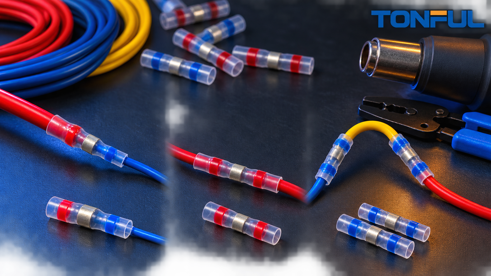

There are three legitimate ways to transition between different conductor sizes: use one step-down butt connector, use one standard butt splice when both conductors fall within its documented range, or add a short jumper and make two standard splices. These architectures may look similar on a schematic, but they create different requirements for wire fit, crimp operations, tooling, routing length, inspection, documentation, and inventory.
The correct decision is not “which connector is strongest?” in isolation. It is which complete wire-connector-tool-process combination can be specified, installed, verified, and serviced consistently.
Splice Bodies and Crimp Terminations
“Joint count” is too ambiguous for this comparison. A butt-splice body has two crimped wire terminations. A jumper architecture has two splice bodies and four terminations.
| Solution | Splice bodies | Crimp terminations | What production must control |
|---|---|---|---|
| Step-down butt splice | 1 | 2 | Large-end crimp and small-end crimp |
| Standard butt splice | 1 | 2 | Two terminations within the same approved barrel range |
| Jumper plus two standard splices | 2 | 4 | Four terminations across the original wires and jumper |
This count does not prove that one option has a particular field-failure rate. It shows the number of splice bodies and crimp terminations that production must install, inspect, document, and, where required, test.
Full Engineering Comparison
| Comparison dimension | Step-down butt connector | Standard butt splice | Jumper plus two standard splices |
|---|---|---|---|
| Conductor-size fit | Two intentionally different barrel ranges | Both wires must fit the documented range of one standard connector | Jumper is selected so each standard splice receives compatible wire sizes |
| Splice bodies | 1 | 1 | 2 |
| Crimp terminations | 2 | 2 | 4 |
| Crimp operations | Normally one operation per end | One operation per end | Four operations total |
| Tool / cavity requirement | May require different cavities or settings for the two ends | Often one approved cavity or setting when both ends use the same range | May use established standard cavities, but each of four terminations must be controlled |
| Installed length | Usually shortest of the three transition architectures | Compact when technically valid | Longest because it includes two splice bodies, jumper length, and routing allowance |
| Sealing method | Depends on construction: uninsulated, insulated, or adhesive-lined heat shrink | Depends on the selected standard splice | Each splice body needs its specified protection; the jumper section must also suit the environment |
| Primary inspection points | Two conductor insertions and two crimps, plus seal where used | Two conductor insertions and two crimps, plus seal where used | Four insertions and four crimps, plus two seals where used |
| Rework / service | Replace the single splice body and trim affected wire length | Replace the single splice body if the standard range remains valid | One splice may be replaced independently, but available wire length and documentation must support the repair |
| Material and inventory complexity | Requires a reducing-splice SKU and approved tooling | Uses a common standard splice SKU when wire ranges overlap | Uses two standard splice bodies plus controlled jumper wire and potentially two connector sizes |
| Required drawings and validation | Two-end wire combination, tool/cavity, strip length, crimp criteria, and environmental protection | Approved conductor range, tool/cavity, strip length, and protection | Two splice specifications, jumper wire specification and length, four termination controls, and routing definition |
| Best fit | Purpose-built unequal wire transition in limited space | Both conductors genuinely share one qualified range | No approved reducing connector exists, or the jumper provides a documented manufacturing or service benefit |
| Main limitation | Availability and two-end process validation | Unsafe when one wire falls outside the qualified barrel range | Adds another splice body and two additional crimp terminations that production must inspect and control |
When a Step-Down Connector Fits Best

A step-down connector is usually the most direct architecture when the two wires require different barrel ranges and the transition must remain compact. The larger end is selected for the larger conductor and the smaller end for the smaller conductor. This avoids treating the smaller wire as if it were inside a barrel range that was designed only for the larger wire.
The benefit is not merely appearance. Conductor compaction, strand containment, crimp height, and pull performance depend on matching each barrel to the actual wire and approved die. A reducing splice may therefore require one cavity or setting for the large end and another for the small end. Review TONFUL’s step-down butt connector guide before selecting a family.
A step-down connector is not automatically valid for every large-to-small combination. Confirm conductor material, strand construction, insulation diameter, strip length, barrel range, tool, environmental protection, and application restrictions.
When a Standard Butt Splice Is Enough
A standard connector is appropriate if the manufacturer’s approved conductor range includes both wires and the documented crimp system can produce acceptable terminations at both ends. For example, two conductors can have different nominal sizes yet still fall within one connector’s qualified range. In that case, a step-down part may add no technical benefit.
The decision must come from the terminal application specification or controlled engineering documentation. Insulation color, a generic red/blue/yellow convention, or visual fit cannot establish conductor compatibility.
Conversely, do not place an undersized wire in an oversized barrel and fold the conductor, double it back, or add loose strands to fill space. These workarounds create uncontrolled geometry. TONFUL’s guide to preventing wire birdcaging explains one common preparation problem.
When a Jumper Makes Sense
A jumper transition places a controlled intermediate wire between the original conductors. Each end of that jumper is selected to fit a standard butt-splice range. It may be justified when:
- The plant already has a validated standard splice system.
- The step-down combination is unavailable.
- Service instructions require replaceable sections.
- The additional length supports an approved routing or service requirement.
- The two splices can be inspected and protected.
- The jumper wire specification and cut length can be controlled as part of the harness bill of materials.
The tradeoff is specific and countable: compared with a one-body solution, the jumper adds another splice body and two additional crimp terminations that production must inspect and control. It also adds jumper cutting, stripping, identification, routing, and inventory requirements. This does not by itself establish a higher failure rate, but it does increase the number of controlled manufacturing results.
Installed Length and Harness Routing
A step-down or standard butt splice normally creates one compact inline transition. A jumper requires enough wire between two splice bodies for tooling access, bend control, sealing, and any required stagger. Do not reduce the jumper to a length that forces sharp bends or places rigid splice bodies next to each other without routing approval.
Evaluate the complete installed envelope, not only connector-body length:
- Wire strip and insertion zones
- Crimp-tool access
- Heat-shrink recovery area where applicable
- Minimum bend radius and strain relief
- Harness covering, clip, conduit, or branch location
- Service access and available wire length for future repair
TONFUL’s wire harness protection methods guide explains how routing and protective coverings affect the finished assembly.
Sealing and Environmental Protection
“Butt connector” describes the electrical splice architecture, not a universal environmental rating. Any of the three options may be uninsulated, nylon-insulated, separately sleeved, or supplied with adhesive-lined heat shrink, depending on the approved product system.
For a jumper, both splice bodies need the required environmental protection. The jumper insulation must also be compatible with temperature, fluids, abrasion, and routing conditions. One sealed connector does not protect a second unsealed termination.
Inspection and Validation Documents
For each crimp termination, define wire part number, connector part number, strip length, insertion criteria, tool and cavity, crimp orientation, dimensional control, and visual acceptance. Add pull-force, resistance, cross-section, sealing, or environmental tests when required by the product or customer specification.
A step-down splice needs evidence for both unequal ends. A standard splice needs evidence that both wires are inside its qualified range. A jumper needs two controlled splice specifications plus the jumper wire part number, cut length, routing, and four termination records.
Tooling and Inspection Differences

One step-down splice may need two die cavities or two controlled tool settings. One standard splice may use one approved cavity when both conductors share a range. A jumper may use established standard tools, but it applies those processes across four terminations. Count each termination in capacity, inspection sampling, destructive-test planning, and operator instructions.
Molex’s official Quality Crimp Handbook emphasizes measurement and process control rather than judging a crimp by appearance alone.
For quality planning, use TONFUL’s crimping tool calibration guide and crimp pull-force testing guide. Pull-force values, crimp-height windows, and resistance limits must come from the applicable connector, wire, tool, and customer documentation rather than from a generic comparison.
Material, Inventory, and Cost Implications
A step-down connector introduces a specialized SKU but can remove the jumper wire and second splice body. A standard splice is usually simplest when technically valid. A jumper can preserve an established standard-terminal process, but its cost model should include two connectors, jumper wire, cutting and stripping, four crimp operations, two sealing operations where required, inspection, documentation, and installed space.
Compare total controlled assembly cost instead of connector unit price alone. Also review forecast volume, minimum order quantity, spare-tooling needs, service stock, label complexity, and the risk of operators selecting the wrong combination.
Rework and Serviceability
Any crimped butt splice is generally replaced rather than reused. A one-body splice usually requires cutting out one connector and consuming some wire length. A jumper may allow one side to be replaced independently, but only if the remaining jumper and original conductor retain adequate length and the repair instruction permits it.
Do not claim that the jumper is inherently easier to repair. Serviceability depends on access, available wire, sealing, harness covering, approved repair limits, and whether replacement parts and instructions are available.
Selection Checklist
- Are both conductors inside one standard connector’s documented range?
- Is there a validated step-down combination for the exact wire constructions?
- Which tool and cavity are required for every termination?
- Is there enough routing and tool-access space for one or two splice bodies?
- What sealing method is required at each splice body?
- How many crimp, insertion, seal, and inspection results must production control?
- Which drawings, application specifications, and validation reports govern the design?
- How will each option affect material, tooling, work-in-process, and service inventory?
- Does the end-product specification restrict production splices or field repairs?
- Which option has the lowest documented total assembly cost while meeting all requirements?
The IPC/WHMA-A-620 overview can help teams structure workmanship requirements.
Choose the Architecture Before the Part Number
Use a standard butt splice when both conductors truly fit its validated range. Use a step-down butt connector when unequal barrel sizing solves the transition with one splice body and two controlled terminations. Use a jumper when no approved reducing combination exists or when an established two-splice process provides a documented manufacturing, routing, or service advantage that justifies two bodies and four terminations.
Share both wire specifications, jumper proposal where applicable, routing envelope, environmental protection, tooling, validation requirements, and annual volume with TONFUL. Request drawings and crimped samples for the complete wire-tool combination before production approval.