
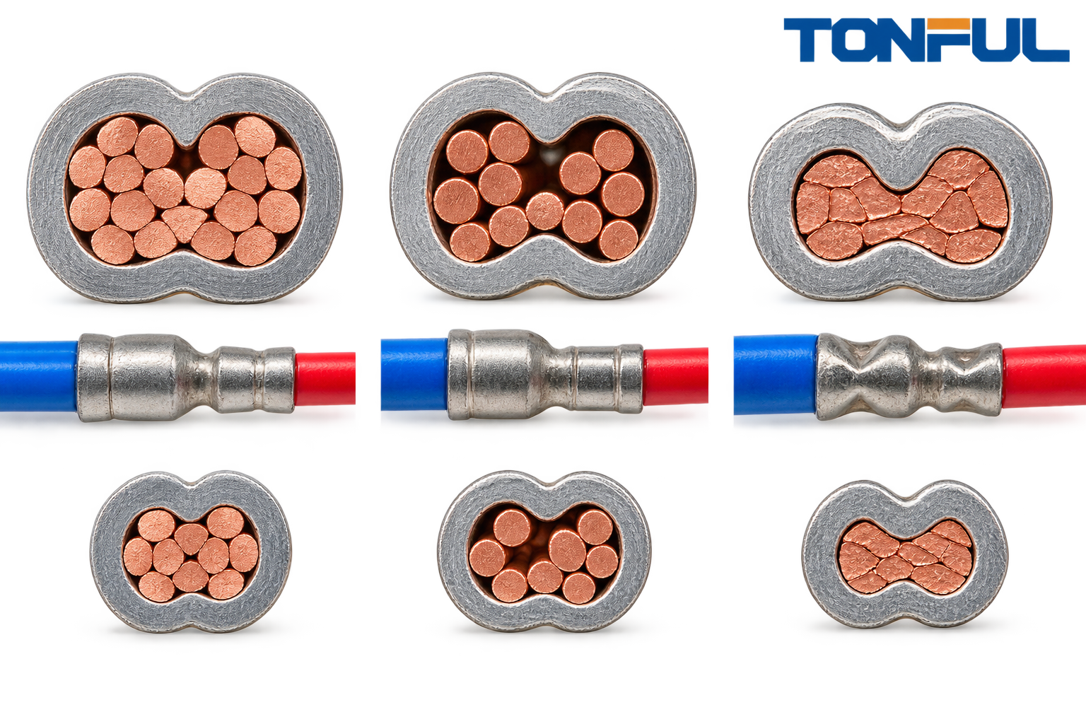
A polished cross-section reveals how the barrel and conductor were compacted during crimping. For a step-down butt splice, the large and small ends must be sectioned and evaluated separately because each interface has different wire area, barrel geometry, and tooling.
A photograph alone is not an acceptance specification. Compare every section with the terminal supplier’s approved criteria, crimp-height window, wire construction, and qualification data.
A good cross-section is therefore not simply the image with the fewest visible gaps. It is a representative, correctly prepared section whose measured features agree with the approved product and process specification. The evaluator must know which end was cut, where the cut was taken, which wire and tool produced it, and whether preparation introduced artifacts.
Define the Analysis Plan First
Before cutting samples, define the purpose: design qualification, process-window development, first-piece approval, periodic monitoring, tooling maintenance, change validation, or failure analysis. The purpose determines sample selection, section location, measurements, and disposition. A qualification study may require several settings and samples, while a failure investigation should compare suspect pieces with known-good controls from the same product family.
The plan should identify connector and wire part numbers, revisions, lot IDs, each end, tool and cavity, setup, operator or machine, section plane, preparation method, equipment, measurement calibration, image magnification, characteristics, limits, and acceptance-source document. Do not create universal void, compression, or symmetry limits when the drawing or approved crimp specification does not provide them.
Prepare a Representative Sample
Record connector lot, wire lot, tool, die cavity, setting, measured crimp height, and operator. Cut the sample at the specified conductor crimp location without distorting it. Mount, grind, polish, and etch only according to an approved laboratory method.
TONFUL’s article on tensile testing and metallographic analysis provides broader context.
Representative sampling starts before mounting. Select samples across relevant machines, cavities, shifts, material lots, and process settings. Preserve the complete splice until its identity and external condition are recorded. Mark the small and large ends permanently, photograph the sample, measure crimp height at the approved location, and document any pull or resistance sample relationship. Never section the only failed assembly before deciding whether nondestructive evidence is needed.
Cutting heat, blade pressure, mounting force, grinding direction, polishing drag, edge rounding, pull-out, staining, and over-etching can imitate product defects. Use progressive preparation and stop when boundaries are clear. If a suspicious crack or void changes between polishing stages, investigate whether it is a preparation artifact. Keep raw images and preparation records rather than saving only an annotated final picture.
Schleuniger’s official crimp cross-sectional analysis guidance describes a preparation workflow that includes cutting, grinding, polishing, electrolytic staining, and optical analysis. Use the approved laboratory method and equipment for the actual termination; this source does not establish acceptance limits for a TONFUL splice.
Measurement System and Image Control
The microscope and image software must be suitable for the feature being evaluated. Record calibration status, scale verification, magnification, illumination, and measurement method. Use MSA or another approved measurement-system study when quantitative section measurements control product acceptance. A scale bar embedded by calibrated software is more useful than an unexplained magnification label.
Control image processing. Brightness and contrast adjustments should not hide boundaries, fill voids, or remove cracks. Preserve the original image, identify any enhancement, and use consistent orientation so large- and small-end comparisons cannot be accidentally reversed.
What to Examine

Conceptual illustration only—not an acceptance standard or laboratory micrograph. The labels identify inspection concepts and section locations; they do not supply product dimensions, measured values, or acceptance limits.
Evaluate:
- All intended strands captured inside the barrel
- Uniform strand distribution and compaction
- Appropriate barrel closure and seam behavior
- Symmetry relative to the approved die profile
- Voids and uncompressed areas
- Strand cutting, flattening, or severe deformation
- Barrel thinning, cracking, folding, or flash
- Evidence of contamination or plating damage
Also examine conductor position, barrel support at the die-contact zones, material displacement, seam interlock or closure behavior, transition into uncrimped material, and any insulation-support feature visible in the selected plane. Not every feature can be assessed in one cut. If the first plane misses the critical region, prepare additional sections at defined locations rather than drawing a broad conclusion from an unrepresentative slice.
| Feature | Evidence to record | Acceptance source |
|---|---|---|
| Strand capture and distribution | Count/position where method permits, annotated image | Drawing or crimp specification |
| Compaction and voids | Defined measurement method and locations | Approved qualification criteria |
| Crimp geometry and symmetry | Width, height, profile, die-contact regions | Tool/application specification |
| Barrel integrity | Cracks, folds, thinning, flash, seam condition | Product drawing/visual standard |
| Conductor integrity | Cut, missing, displaced, or severely damaged strands | Workmanship specification |
| Surface condition | Contamination, corrosion, abnormal plating damage | Material/product specification |
Do not expect the small and large ends to have identical pictures. They should each match their own validated geometry.
The unequal barrels may use different cavity profiles, wall geometry, and conductor constructions. Evaluate each against its own approved limits and then compare process consistency. Similar-looking compaction percentages do not automatically mean equivalent mechanical or electrical performance.
TE Connectivity’s official Crimp Quality Guidelines illustrates crimp cross-section characteristics, strand distribution, voids, flash, cracks, and incorrect adjustment. TE explicitly states that its figures are schematic and that the relevant product and application specification takes precedence. Apply the same evidence discipline here; do not transfer TE-specific geometry or limits to a TONFUL product.
Common Cross-Section Defects
Signs of Undercrimping
Large voids, limited strand deformation, an open barrel profile beyond the approved condition, and low mechanical retention can indicate insufficient compaction. Confirm with measured crimp height and pull data before assigning cause.
Possible causes include an oversized cavity, excessive shut height, wrong setting, incomplete tool cycle, hard or undersized conductor, missing strands, incomplete insertion, barrel springback, or wrong terminal. Immediate containment should identify the affected tool, cavity, setup interval, and lots. Confirm root cause by reproducing the condition under controlled changes rather than adjusting the tool until one photograph appears better.
Signs of Overcrimping
Excessive strand damage, severe barrel thinning, cracks, sharp flash, or an abnormally low crimp height can indicate overcompression or die mismatch. More compression does not always mean lower resistance or higher strength.
Possible causes include an undersized cavity, low shut height, wrong locator, excessive press setting, doubled operation, off-center terminal, oversized conductor, or incorrect barrel material. A crack may also result from material, seam, plating, or forming defects. Compare unused connectors, forming-lot records, and sections made with approved settings before blaming the crimp operation.
The official Molex Quality Crimp Handbook explains the relationship among crimp height, visual condition, pull force, and process setup.
Other Conditions a Cross-Section Can Reveal
An asymmetric section can indicate off-center loading, terminal rotation, locator error, uneven die wear, or a section plane that was not perpendicular. Escaped strands may originate during stripping, insertion, or crimp closure. Folded barrel material can indicate cavity mismatch or poor pre-form geometry. Contamination between strands may point to handling, conductor oxidation, process residue, or preparation debris; confirm composition before assigning cause.
A visually dense section can still be unacceptable if strands were cut, the barrel cracked, the conductor was not fully inserted longitudinally, or electrical resistance is unstable. Conversely, a visible void is not automatically a failure unless it violates an approved criterion or correlates with performance evidence. Use disciplined language such as “observed,” “measured,” and “outside the specified limit” instead of declaring a cause from appearance alone.
Compare Both Ends

Conceptual illustration only—not an acceptance standard or laboratory micrograph. The six labeled cells show qualitative differences for training. They have no traceable production sample, wire, cavity, crimp-height result, or calibrated dimensional scale.
| Observation | Small end question | Large end question |
|---|---|---|
| Strand capture | Did fine strands fold or escape? | Did all larger strands enter fully? |
| Compaction | Is the cavity too large? | Is the tool force and height controlled? |
| Barrel condition | Did a small cavity create cutting? | Did misalignment create fold or flash? |
| Symmetry | Is the connector centered in its die? | Is the large barrel fully supported? |
| Voids | Does geometry match approved samples? | Are voids caused by strand construction? |
Use a Failure-to-Evidence Workflow
- Quarantine the suspect lot and preserve samples.
- Review connector, wire, tool, cavity, setup, operator, and inspection traceability.
- Perform external visual inspection and verify strip length and insertion evidence.
- Measure crimp height and width at both ends using the approved method.
- Review pull-force failure mode and results for each end where applicable.
- Measure resistance with the specified four-wire method when required.
- Section suspect and known-good controls at the defined locations.
- Compare measurements with drawing, application specification, and qualification data.
- Reproduce the suspected cause through a controlled trial.
- Update PFMEA, control plan, work instruction, maintenance, or training after confirmation.
This sequence prevents destructive sectioning from erasing earlier evidence and keeps the investigation connected to production records.
TONFUL’s step-down butt connector failure guide helps connect section evidence with stripping, insertion, tooling, bending, sealing, and environmental causes without treating the micrograph as the only source of truth.
Cross-Section Is One Part of Validation
Pair section analysis with visual inspection, crimp height, pull force, and electrical resistance. Cross-sections are destructive snapshots; they do not replace ongoing process monitoring.
TONFUL’s crimp pull-force testing guide, tool calibration guide, and wire harness continuity guide cover complementary evidence.
Crimp height is a process measurement, pull force is a destructive mechanical result, resistance evaluates electrical behavior under a defined method, and cross-section analysis shows internal geometry at one plane. None replaces the others. Qualification and investigation should combine the evidence required by the product plan; routine production controls should then monitor the characteristics proven to control performance.
Cross-Section Record Template
| Record field | Result |
|---|---|
| Sample ID; connector/wire lots and revisions | |
| Small or large end; section location | |
| Tool, die, cavity, machine, setting | |
| Operator, date, shift, process condition | |
| Crimp height/width result and limit | |
| Preparation method and laboratory | |
| Microscope, calibration, magnification, scale | |
| Strand capture/distribution observation | |
| Void/compaction method and result, if specified | |
| Barrel, seam, crack, flash, and damage observations | |
| Pull and resistance references, if required | |
| Acceptance-source document and revision | |
| Pass/fail, reviewer, date, evidence filename |
Record actual values and observations, not only pass/fail. Link every image to the physical sample and retain the unedited original. If a result is invalid because the section plane or preparation was defective, document the reason and select a new identified sample; do not quietly replace the image.
Build a Golden Sample Library
Retain approved sections for each connector, wire pair, tool, and cavity. Include measured data and revision status. Use failed sections for training, but do not let an unlabeled photograph become an uncontrolled acceptance limit.
Store golden images under document control with approval, revision, scale, wire construction, tool, cavity, measured crimp height, and source specification. Review the library after material, terminal, wire, tooling, method, or acceptance changes. Physical mounted samples can degrade or become separated from labels, so maintain durable identification and digital records.
Share the exact wire pair, connector, tooling, measurements, and failure symptom with TONFUL when requesting section analysis or process review.