
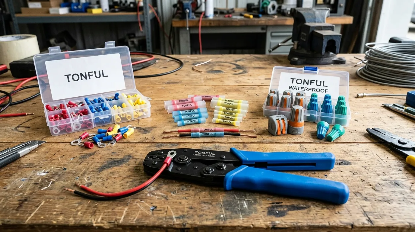
A wire terminal is the conductive endpoint that terminates a stranded conductor and joins it to a stud, screw, blade, mating contact, or another wire. It looks unremarkable, yet it is the single point where electrical energy changes hands — and where most circuit failures actually originate. For B2B buyers specifying wire terminals across automotive harnesses, industrial control panels, and appliances, the terminal’s geometry, base alloy, plating, and crimp profile determine whether a connection survives ten years of vibration or fails in the first month.
This guide maps the major wire terminal families, their application fit, the material and plating trade-offs, and the acceptance standards that separate a compliant crimp from a latent defect.

What Is a Wire Terminal?
A wire terminal is a metal fitting — usually copper or brass, tin- or nickel-plated — crimped or soldered onto the stripped end of a stranded wire. Once attached, it provides a standardized interface: a ring that bolts to a stud, a fork that slides under a screw, a flat blade that pushes into a receptacle, or a barrel that splices two conductors end-to-end. The terminal carries current, resists pull-out force, and bridges the transition from flexible stranded copper to a rigid termination point. For a deeper definition, see our primer on what a crimp terminal is.
Terminals differ from general wire connectors in one key respect: a connector typically joins two conductors inside an insulating body, while a terminal provides an endpoint that mates with a fixed device. Both rely on crimping, but the mechanical and application logic diverge — which is why selecting the wrong family is the most common sourcing mistake TONFUL sees in incoming audits.
Core Wire Terminal Types and Their Applications
Every wire terminal family solves a specific mechanical problem. Matching the family to the load, environment, and service requirement is the first engineering decision.

Ring Terminals
A ring terminal forms a closed circular lug that passes over a stud or screw and is secured with a nut. Because the ring cannot slip off even if the fastener loosens, it is the default choice for high-vibration and safety-critical power connections — battery grounds, mains earth bonding, and industrial busbar terminations. TONFUL’s ring insulated terminals and heat shrink ring terminals cover the full AWG range with vinyl, nylon, and adhesive-lined heat-shrink insulation options.
Spade (Fork) Terminals
A spade terminal uses an open fork that slides under a screw head, allowing installation or removal without fully removing the fastener. This speeds up panel wiring and maintenance, but the open design means a spade can detach if the screw backs out — so it is avoided on primary power runs and high-vibration assemblies. For selection guidance, see ring vs spade terminals and our fork terminal applications guide.
Butt Splice Terminals
A butt splice is a barrel that joins two stripped wires end-to-end. It is the workhorse for harness repair, wire extension, and sealed in-line joints. Heat-shrink butt splices add an adhesive-lined sleeve that forms a waterproof seal, making them the standard for marine and outdoor wiring. Compare options in our butt splice connector applications guide and the heat shrink butt connector guide.
Quick-Disconnect (FASTON) Terminals
Flat blade terminals — widely known by the FASTON trade name — push together for rapid connection and disconnection. They dominate appliance, switch, relay, and HVAC wiring where a single conductor mates to a device tab and periodic service is expected. Sizing and application detail is in our quick-disconnect terminals guide.
Cord-End Ferrules
A ferrule is a tin-plated copper sleeve that compresses stranded wire into a rigid pin for insertion into a screw-clamp terminal block. Without a ferrule, a screw clamp can splay, damage, or cold-flow stranded conductors — a hidden failure mode in European-style terminal blocks. Ferrules are mandatory in many IEC-compliant panel builds; see cord-end terminal applications and wire ferrule terminal applications.
Piggyback Terminals
A piggyback terminal stacks a second blade contact on top of a standard quick-disconnect, allowing one feed wire to power two devices without cutting or splicing the harness. It is widely used in automotive fuse-box tap-offs and accessory circuits — covered in our piggyback terminal applications guide.
The table below summarizes the application fit for each family.
| Terminal Type | Typical AWG Range | Primary Application | Vibration Resistance | Reusability | Key Use Case |
|---|---|---|---|---|---|
| Ring | 10–22 | Power ground, stud termination | Excellent | Medium (bolt removable) | Battery, earth, busbar |
| Spade/Fork | 16–22 | Panel screw terminals | Moderate | High | Control panels, terminal blocks |
| Butt Splice | 10–22 | Wire-to-wire splice | Good (sealed) | None | Harness repair, extension |
| Quick-Disconnect | 16–22 | Device tap-off | Moderate | High | Appliances, relays, switches |
| Cord-End Ferrule | 18–10 | Screw-clamp terminal block | Good | None | IEC panel builds, PLC I/O |
| Piggyback | 16–20 | Split signal without cutting | Moderate | High | Automotive accessory circuits |
| Heat-Shrink Sealed | 10–22 | Wet/harsh environment | Excellent | None | Marine, outdoor, direct burial |
Material and Plating: What Actually Carries the Current
A wire terminal’s electrical and corrosion performance is governed less by its shape than by its base metal and surface finish. The great majority of terminals are copper or brass, plated to prevent oxidation and to reduce contact resistance.
| Base Material | Plating | Conductivity (IACS %) | Corrosion Resistance | Typical Application | Cost |
|---|---|---|---|---|---|
| Copper (C11000) | Tin | ~100 | Good | General-purpose, automotive | Low |
| Copper | Nickel | ~100 | Excellent | High-temperature, engine bay | Medium |
| Copper | Silver | ~100 | Very good | High-current, low-contact-resistance | High |
| Brass (C26000) | Tin | ~28 | Good | Stamped contacts, low-cost | Low |
| Copper | None (bare) | ~100 | Poor | Indoor, dry, non-critical | Lowest |
| Steel | Zinc/nickel | ~15 | Moderate | Mechanical, non-current | Low |
Tin plating is the volume default because it is solderable, low-cost, and adequate for most environments below 125°C. Nickel steps in for engine-bay and high-temperature duty. Silver offers the lowest contact resistance for high-current power electronics but costs more and is vulnerable to sulfidation. The trade-offs are discussed in detail in copper vs brass terminals and tin-plated copper terminal corrosion standards.
For wet, salt-spray, or direct-burial environments, plating alone is insufficient — an adhesive-lined heat-shrink seal is required. TONFUL’s heat shrink terminals and heat shrink terminal manufacturer lines are engineered for exactly these conditions.
Wire Terminal Selection by Industry
Different industries stress terminals in different ways, and the correct selection reflects the dominant failure mode each environment produces.
| Industry | Dominant Stress | Preferred Terminal | Sealing Requirement | Governing Standard |
|---|---|---|---|---|
| Automotive (passenger) | Vibration, temperature cycling | Sealed ring, heat-shrink butt | IP-rated or adhesive-lined | USCAR-21, LV214 |
| Heavy-duty truck | Vibration, contamination | Sealed ring, sealed quick-disconnect | IP67+ | SAE J2222 |
| Marine | Salt spray, moisture | Adhesive-lined heat-shrink | IP67–IP68 | ABYC E-11 |
| Industrial control panel | Repeated maintenance | Ferrule, spade, ring | None (panel-protected) | IEC 60998, UL 486A-B |
| Appliance | Cost, assembly speed | FASTON quick-disconnect | None | UL 310 |
| Solar/utility | UV, thermal cycling | Tin-plated copper ring | UV-rated insulation | UL 486D |
| EV battery | High current, thermal | Heavy-duty copper lug | Heat-shrink sealed | ISO 6469, IPC-A-620 Class 3 |
The IPC/WHMA-A-620 wire harness standard is the cross-industry acceptance reference for crimped terminations, while CE vs UL certification and the UL 486 vs UL 310 comparison clarify which compliance regime applies to a given market.
Crimp Geometry and Acceptance Standards
A terminal’s reliability is finalized at the crimp. The crimp must cold-weld the strands to the barrel without severing them, leave a measurable bellmouth at the transition, and hold the insulation in a support crimp that resists flex fatigue. Three standards define acceptance: IPC/WHMA-A-620 for harness workmanship, UL 486A-B for North American wire connectors, and USCAR-21 for automotive terminals.

A compliant crimp meets minimum pull-force values that scale with wire gauge. The table below gives representative minimum pull-out forces per IPC/WHMA-A-620 Class 2 (general industrial).
| AWG | Cross-Section (mm²) | Min. Pull Force (N) | Typical Crimp Height (mm) | Insulation Color Code |
|---|---|---|---|---|
| 10 | 5.26 | 310 | 4.8–5.2 | Yellow |
| 12 | 3.31 | 250 | 3.9–4.3 | Yellow |
| 14 | 2.08 | 180 | 3.2–3.6 | Blue |
| 16 | 1.31 | 130 | 2.6–3.0 | Blue |
| 18 | 0.82 | 90 | 2.1–2.5 | Red |
| 20 | 0.52 | 60 | 1.7–2.0 | Red |
| 22 | 0.32 | 45 | 1.4–1.7 | Red |
These values assume stranded copper, no pre-tinning, and a calibrated tool — three conditions that fail more often than they should in the field. The crimp terminal color code chart and the AWG to metric conversion guide help buyers map gauge to color and cross-section correctly, while our crimp pull force testing guide documents the validation method.
Installation Best Practices
Reliable terminal performance comes down to a handful of disciplined steps. Strip the insulation to the exact length marked on the terminal barrel — too short and strands are unsupported, too long and bare copper extends past the crimp. Never pre-tin stranded wire before crimping; tinned strands cold-flow under vibration and loosen the joint, a defect IPC/WHMA-A-620 explicitly prohibits. Use a calibrated ratcheting or hydraulic tool with the correct die profile for the terminal family, and verify the crimp height against the terminal datasheet.

For field work, tool maintenance matters as much as technique — a worn die produces under-crimps that pass visual inspection but fail pull tests. See our guidance on crimping tool maintenance and calibration and how to properly crimp electrical wires. The perennial question of whether crimping or soldering is superior is addressed in solder vs crimp — the short answer is that for stranded conductors subject to vibration, a properly engineered crimp outperforms solder, which crystallizes and fails under flex.
Choosing the Right Wire Terminal
Selecting a terminal is a sequence of narrowing decisions: fix the current and wire gauge first, then the environment, then the service requirement.

Start from the terminals and connectors manufacturer catalog, match the terminal to the dominant stress from the industry table, and confirm compliance against the applicable standard. For mixed-gauge splices, specify a step-down butt connector; for non-insulated high-current studs, use square non-insulated terminals; for automotive harness builds, source from the automotive terminals and connectors range. When the requirement is custom, TONFUL’s custom wire harness assembly service builds terminated looms to print.
Conclusion
A wire terminal is a small component with an outsized role: it is where the conductor meets the system, and where reliability is won or lost. The right terminal family, the right base metal and plating, and a standards-compliant crimp are the three levers that determine whether an electrical connection lasts decades or fails on the test bench. TONFUL Electric manufactures the full wire terminal range — from insulated ring and spade terminals to sealed heat-shrink splices, ferrules, and quick-disconnects — to IPC/WHMA-A-620, UL 486, and USCAR-21 acceptance criteria. Explore the complete wire terminal manufacturer range or contact TONFUL for OEM and custom harness quotations.
FAQ
What is a wire terminal used for? A wire terminal terminates the end of a stranded conductor and provides a standardized interface — ring, fork, blade, or barrel — for connecting to a stud, screw, device tab, or another wire. It carries current, resists pull-out, and bridges flexible wire to a rigid termination.
Ring or spade terminal — which should I use? Use a ring terminal for high-vibration or safety-critical power connections, because the closed lug cannot slip off even if the fastener loosens. Use a spade/fork terminal where fast installation and removal matter and vibration is low, such as inside a protected control panel. See our ring vs spade selection guide.
Can I solder a wire terminal instead of crimping? For stranded conductors subject to vibration, a properly engineered crimp outperforms solder. Solder wicks into the strands by capillary action and creates a rigid transition that crystallizes and fractures under flex. IPC/WHMA-A-620 prohibits pre-tinning strands before crimping. Read the full analysis in solder vs crimp.
What do the red, blue, and yellow terminal colors mean? The color indicates the wire gauge range the terminal accepts: red for 18–22 AWG, blue for 14–16 AWG, and yellow for 10–12 AWG. This NEMA/IEC color code is consistent across ring, spade, butt, and quick-disconnect families. See the crimp terminal color code chart.
Are heat-shrink terminals waterproof? Adhesive-lined heat-shrink terminals form a waterproof seal rated to IP67 or higher when properly installed with a heat gun. They are the standard for marine, outdoor, and direct-burial wiring. Browse the heat shrink terminal range.